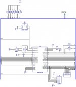
I3 is the USB interface.
I've been having some issues reflowing with these Chinese boards so I hand soldered this one. No fun!😡
I'm not sure why people are using the Ebay stuff either. These things work great. The programming might be scaring some off but you just dump it on and go. No real skills required.
The last version was more typical "DIY friendly". I soldered them with my
fat brass tip and fat solder (smd).
I acknowledged that "Vzaichenko tech" was SOTA in the "Badger thread" ,
recommended this fine project to compliment a perfect amp (Badger =100%) !
OS
The last version was more typical "DIY friendly". I soldered them with my
fat brass tip and fat solder (smd).
I acknowledged that "Vzaichenko tech" was SOTA in the "Badger thread" ,
recommended this fine project to compliment a perfect amp (Badger =100%) !
OS
You need to add bias connectors to your output boards to make them that much easier to connect. I did it with my sub amp.
You need to add bias connectors to your output boards to make them that much easier to connect. I did it with my sub amp.
The "honey badger" already has "TP1/2" posts for the over current hookup.
Thermal could just be another hole in the heatsink .
Everything else is just power supply wiring.
Edit - one builder even ran wires off the badger board to add V/I limiters.
OS
Diy goes commercial!!!!!!Almost ready for testing. I need to make up an ISP cable next.

do you sell the relay boards
jwilhelm,
Are you using Atrium as you PCB lay out designer?
I would like to buy some relay boards if they are available or get some made?
Matt
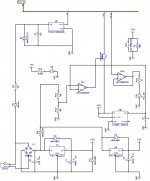
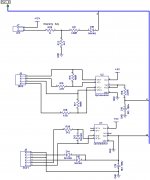
Here's the relay.
jwilhelm,
Are you using Atrium as you PCB lay out designer?
I would like to buy some relay boards if they are available or get some made?
Matt
BTW jwilhelm your relay board schematic shows the base of Q5 pulled up to +5v.
+5v is not used anywhere else on the board.
Cheers
Matt
+5v is not used anywhere else on the board.
Cheers
Matt
I've been using DipTrace to design these boards
The relay board and the latest control board aren't tested yet. They've been updated a bit since the schematics and will likely have a couple bugs to work out. They are a huge change from previous versions. Gerbers will be available after they are debugged.
The relay board and the latest control board aren't tested yet. They've been updated a bit since the schematics and will likely have a couple bugs to work out. They are a huge change from previous versions. Gerbers will be available after they are debugged.
Gerbers will be available after they are debugged.
"Patience Grasshopper". Thankz. I look forward to seeing how it performs.
Sent from my SM-N9005 using Tapatalk
Jeff, kool lites is right - R12 is referenced to +5V, but there is no +5V rail on DC offset sensor / SS relay board. So you need to either bring it there from the main board, or reference to +12V rail with appropriate R12 value increase. R12 = 12K will be good in this case.
Cheers,
Valery
Cheers,
Valery
Jeff, kool lites is right - R12 is referenced to +5V, but there is no +5V rail on DC offset sensor / SS relay board. So you need to either bring it there from the main board, or reference to +12V rail with appropriate R12 value increase. R12 = 12K will be good in this case.
Cheers,
Valery
I saw that when I posted the schematic and I think I connected it to 12V. I'll see when I get a chance to populate the board. I'm battling with the control board right now. I can't burn the bootloader for some unknown reason.
I am trying to find the schematic(s) that Jwilhelm and Vzaichenko are building from. Keep up the Great work Gentlemen. I hope to put this on a system I am building with Damir's CFA boards. Thanks again.
I am trying to find the schematic(s) that Jwilhelm and Vzaichenko are building from. Keep up the Great work Gentlemen. I hope to put this on a system I am building with Damir's CFA boards. Thanks again.
What version are you looking for?
I am looking for the one or ones in the recent pictures. Forgive me I am lost in the maze.😉What version are you looking for?
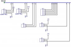
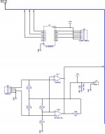
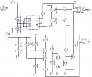
These are still untested. Some passive values will likely change.
Attachments

I saw that when I posted the schematic and I think I connected it to 12V. I'll see when I get a chance to populate the board. I'm battling with the control board right now. I can't burn the bootloader for some unknown reason.
What programmer are you using to load the bootloader? Do you get the correct signature back for the 328?
Sent from my SM-N9005 using Tapatalk
I'm trying to load it with a Uno and also with a parallel adapter. It loaded with the parallel cable, then errored. No sync with the Uno.
I just installed an atmega328 and a crystal on another board and burned the bootloader in a couple seconds so I have an issue with the first board.
These are still untested. Some passive values will likely change.
manual speaker "on" , as well ? that's cool !
OS
manual speaker "on" , as well ? that's cool !
OS
That's the signal from the Arduino but could be manual too.
These are still untested. Some passive values will likely change.
I think, for those who wants to build right now, this is a good version >HERE<
- Home
- Amplifiers
- Solid State
- How to build a 21st century protection board