All the binding posts I've ever used are on 3/4" centers. I'm not sure if there's a standard or not.
Ah, ok. The ones I use now are standalone ones, so I can place them any way I want. 3/4" - good to know.
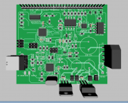
I'm making some progress on the Control board. I still need to swap a few parts. This is on a 3" x 3" board and still plenty of space. I'm going to add connectors for all the analogue inputs. There will likely be some smaller resistors in a few places too.
On the Arduino Uno board they used a SMT crystal with integrated caps on the Atmega328 and a through hole crystal and separate caps for the USB IC. They are both the same frequency. I've been trying to figure out why? The SMT one is a much easier package to route.
On the Arduino Uno board they used a SMT crystal with integrated caps on the Atmega328 and a through hole crystal and separate caps for the USB IC. They are both the same frequency. I've been trying to figure out why? The SMT one is a much easier package to route.
Attachments
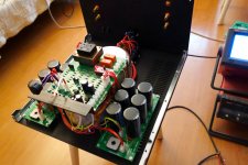
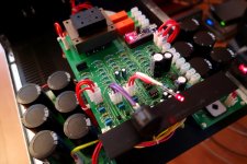
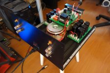
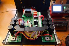
I have finally started assembling the amp in the case.
This is the PSU and the control board - earlier version with the large PCB and mechanical relays (I just had it already soldered some time ago).
Everything works perfectly.
Now the biggest problem is to drill the heatsinks precisely enough...
This is the PSU and the control board - earlier version with the large PCB and mechanical relays (I just had it already soldered some time ago).
Everything works perfectly.
Now the biggest problem is to drill the heatsinks precisely enough...
Attachments

I'm making some progress on the Control board. I still need to swap a few parts. This is on a 3" x 3" board and still plenty of space. I'm going to add connectors for all the analogue inputs. There will likely be some smaller resistors in a few places too.
On the Arduino Uno board they used a SMT crystal with integrated caps on the Atmega328 and a through hole crystal and separate caps for the USB IC. They are both the same frequency. I've been trying to figure out why? The SMT one is a much easier package to route.
SMT rules! 🙂
Yeah, strange about the crystals...
I have finally started assembling the amp in the case.
This is the PSU and the control board - earlier version with the large PCB and mechanical relays (I just had it already soldered some time ago).
Everything works perfectly.
Now the biggest problem is to drill the heatsinks precisely enough...
Drilling the heat sinks is the easy part for me. There must be someone in your area with a milling machine. It's nice not having to custom fit all the holes after drilling.😀
SMT rules! 🙂
Yeah, strange about the crystals...
I like working with SMT. It was great when I used to hand etch. No drilling all those holes in the PC board.
I have finally started assembling the amp in the case.
This is the PSU and the control board - earlier version with the large PCB and mechanical relays (I just had it already soldered some time ago).
Everything works perfectly.
Now the biggest problem is to drill the heatsinks precisely enough...
Looks like a neat amplifier in the making. Dual monoblocks, You don't mess around! What is this going to be?
Looks like a neat amplifier in the making. Dual monoblocks, You don't mess around! What is this going to be?
I'm planning to use CF-FET V2 front-ends with separate Shuntie for each channel, in combination with 5-pair MOSFET Slewmasters. Excellent current delivery capability, when required, for example, when at some frequencies the speaker impedance goes down 😉
A 5 pair Mosfet Slewmonster sounds cool!
I've been thinking of building a CF-Fet V2 with Shuntie attached to it. Less wire is good.
I've been thinking of building a CF-Fet V2 with Shuntie attached to it. Less wire is good.
A 5 pair Mosfet Slewmonster sounds cool!
I've been thinking of building a CF-Fet V2 with Shuntie attached to it. Less wire is good.
Yep, good idea. In my case, I started thinking about Shuntie, when the front-end PCBs were already manufactured 🙂
I have finally started assembling the amp in the case.
This is the PSU and the control board - earlier version with the large PCB and mechanical relays (I just had it already soldered some time ago).
Everything works perfectly.
Now the biggest problem is to drill the heatsinks precisely enough...
Cool , join the crowd .... 🙂
That's how I started , with the power supply / arduino control.
Drilling the heatsinks (without a drill press), was the "hairpulling" part.
Center them output stages , multiple pairs like equal dissipation -
no "hot spots".
OS
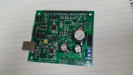
Almost ready for testing. I need to make up an ISP cable next.
so this one has the serial-usb converter built in ?
PS - I'm so surprised the whole "solid state" crowd has NOT broken
down the door to get these projects , they are so reliable and light years
ahead of any Ebay /present project !!! Very good work , Jeff !! 😱
os
Almost ready for testing. I need to make up an ISP cable next.
Fantastic looking!
so this one has the serial-usb converter built in ?
PS - I'm so surprised the whole "solid state" crowd has NOT broken
down the door to get these projects , they are so reliable and light years
ahead of any Ebay /present project !!! Very good work , Jeff !! 😱
os
I3 is the USB interface.
I've been having some issues reflowing with these Chinese boards so I hand soldered this one. No fun!😡
I'm not sure why people are using the Ebay stuff either. These things work great. The programming might be scaring some off but you just dump it on and go. No real skills required.
While researching the ISP cable I figured out we can interface an Arduino directly to the ISP connection and do all the programming through that. No USB required really. If we want to interface this with another front end, we can do that serial through the ISP port as well. I'm learning lots about these as I try new designs.
You should chat with Linuxworks about that. He has some very cool sounding XBee ideas. No USB cables to cause ground loops.
- Home
- Amplifiers
- Solid State
- How to build a 21st century protection board