Hi,
Just in case here it is a link to Pololu store that have a varieties of current sensor modules.
Link:https://www.pololu.com/product/2199
Just in case here it is a link to Pololu store that have a varieties of current sensor modules.
Link:https://www.pololu.com/product/2199
I put my first good test on the protected supply. I ran sine sweeps into a 250W Slewmaster Sub amp at clipping for 15 minutes. The mosfets on the supply board only came up to 76F. 5 degree rise. It's nice having the power off instantly while working on the amp. I never realized how much time we waste waiting for the rail voltage to drop off.
50A is overkill but any smaller rating changes the current leads to tiny wire.
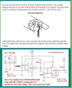
Better to make your own current sensor using a generic hall effect
sensor and coil/toroid (below).
Link - Using Ratiometric Hall Effect Sensors
Avoid proprietary components. Unless you are lazy ... 😀
OS
Attachments
Better to make your own current sensor using a generic hall effect
sensor and coil/toroid (below).
Link - Using Ratiometric Hall Effect Sensors
Avoid proprietary components. Unless you are lazy ... 😀
OS
I like those one because they looked neat. I think I'm going to try them out in the truck I'm building. I need current sensing for the power steps they want under the cab. Also a good project to botch together some Arduino coding to operate it.
Once you scaled the home made one (wiregauge/ferrite/sensor ratio),
it could be as accurate as the integrated one.
The integrated one still has to be scaled to it's application , despite
it's complexity.
Just a thought.
OS
it could be as accurate as the integrated one.
The integrated one still has to be scaled to it's application , despite
it's complexity.
Just a thought.
OS
os, with your idea, having the speaker current going through a coil that saturates because of a magnetic (ferrite) core? does this not affect linearity some how?
i think if you send valery a pm he will send/email you the cam data. you can send the cam data to a pcb fab shop for boards. this way valery can keep track.
i think if you send valery a pm he will send/email you the cam data. you can send the cam data to a pcb fab shop for boards. this way valery can keep track.
Last edited:
What if anything is wrong with this module? I have ordered 2 for testing
Hot 30A Range Current Sensor Module ACS712 ACS712ELC 30A Chip Module for Arduino | eBay
Hot 30A Range Current Sensor Module ACS712 ACS712ELC 30A Chip Module for Arduino | eBay
in the old days maybe 🙂 not to say that you should not strive for second sourcing,Avoid proprietary components. Unless you are lazy ...
the only savoir is to stock up on proprietary components in event of obsolescence.
i am still pissed with maxim for obs the max9739, now have to re-design the portable for one comp. i have one spare that is it, even asia can't find me any. maxim wants me to buy a reel of 5K for a last time buy, = i don't think so, see how it works.
the day is coming and is already happening, when fairchild will drop all your fav small signal bjts/jfets, in to-92, just like toshiba has done, so time to move to smt asap.
Last edited:
Hi,
To: Krisfr
I used the same module but 5 amps. They are easy to read and reduce the components counts. Just 2 analog inputs for both channels. You can easily implement them in any amplifier by just cutting the speakers cables and read the voltage output from the modules. Nothing to it.
To: Krisfr
I used the same module but 5 amps. They are easy to read and reduce the components counts. Just 2 analog inputs for both channels. You can easily implement them in any amplifier by just cutting the speakers cables and read the voltage output from the modules. Nothing to it.
in the old days maybe 🙂 not to say that you should not strive for second sourcing,
the only savoir is to stock up on proprietary components in event of obsolescence.
i am still pissed with maxim for obs the max9739, now have to re-design the portable for one comp. i have one spare that is it, even asia can't find me any. maxim wants me to buy a reel of 5K for a last time buy, = i don't think so, see how it works.
the day is coming and is already happening, when fairchild will drop all your fav small signal bjts/jfets, in to-92, just like toshiba has done, so time to move to smt asap.
I did this for a living , long ago. Jwilhelm wanted current sensing for DC
rails in the PS. I would never run audio through a tiny toroid. 🙄
Larger gauge winding , fewer turns than the image - no saturation.
The hall effect sensor would have to be amplified and scaled.
To sense a sharp 6-10A threshold would be very easy and precise.
For the audio -
I even have some of my old industrial current detectors (trafo's).
Audio just forms the primary by going through the hole. easily
rectified , scaled ( just set a threshold for the arduino trigger).
WAY Superior to monitoring voltage drop across an output Re.
This is the way the factory keeps track of remote motors/fans/pumps.
Current demand would even indicate one in need of service.
OS
I was just thinking about adding those current sensors because they look neat. I'm still thinking current sensing should be done on each individual output pair because of the possibility of thermal runaway.
Hi Valery,
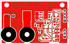
Do you offer the PCB for sale ?
I can send you Gerber files to get your own produced. PM me your email address if you would like them.
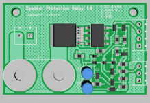
I've been designing a control system with speaker relays and DC detection right at the binding posts. I've run into a bit of a snag. To keep it universal I've layed out individual complete detection modules for each channel. (Jason's idea sounded good after all)
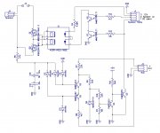
The way the circuit operates presently, The microcontroller needs to see a low input from the DC detect circuit or it will go into shutdown. I like this operation personally because if there is a connection issue anywhere it will shut down.
The issue I have run into is that the microcontroller will require a separate input for each speaker relay module to operate like this. There are 4 available digital IOs available including the RX and TX so it's not a huge issue. My only concern is the extra code that is going to be required to make it operate. Is that going to cause any speed/reliability issues for the Arduino? This could be solved with an AND gate and some jumper selectors for the number of channels but I'm not a fan of jumpers. Too easy to bypass a safety circuit and forget about it that way.
Does anyone have any suggestions on wire to board connectors. .100" headers are a good size but we need something that will last more than a few weeks reliably.
Last edited:
Jeff, this is cool. What is the space between the centers of the speaker terminals? Is there a standard for that or something?
- Home
- Amplifiers
- Solid State
- How to build a 21st century protection board