Next set of measurements were with two 5.6M resistors in series connected in parallel with the 3.4p capacitor (11M2||3.4p)
50: 10.23M, 100: 10.23M, 330: 10.23M, 1000: 9.77M, 3300: 6.51M, 5000: 5.12M, 10000: 2.75M, 20000: 1.49M.
The 11M2 resistor measured at 11.16M on the small DMM's. Making the measurement error 8.3%
Finally, the same 2 transistor 5mA CCS with two 2n3904 transistors:
50: 5.30M, 100: 5.81M, 330: 6.32M, 500: 6.32M, 1000: 6.32M, 2000: 6.14M, 3300: 5.24M, 5000: 4.30M, 10000: 2.56M, 20000: 1.38M, 33000: 934K.
6.32M @ 1KHz, very close to elvees result for 2n3904's, ~5% difference. 😀
The anomaly with the 50 & 100Hz measurements is related to the ~0.4Hz component that becomes apparent on the scope at these frequencies making it difficult to make an accurate measurement at these frequencies. I'm still in the dark as to the source of the 0.4Hz.
Last edited:
I made the test; I first checked the calibration with 1Meg and 10Meg resistors, and it was within a few % (resistors are 5% tol.)
measured at 1Vrms, 20V across the CCS, current 5.0mA (resistors of 39K and 120Ω), transistors are BC 547B Motorola made 16th w. of 1994Code:[U]Freq. (Hz)[/U] [U] Z (MΩ)[/U] 100 28.5 330 16.6 1K 14.2 3.3K 11.7 10K 6.25 20K 3.3
The resistive part of the impedance must be around ~30MΩ, and the capacitive component kicks in at ~1KHz and dominates completely above ~5KHz: the ratio of 10 to 20KHz is almost exactly 0.5
Elvee, If you have the time could you post a schematic of your setup please, even a hand drawing scanned would do, thanks,
Gordon.
It is the transformer setup I posted some days agoElvee, If you have the time could you post a schematic of your setup please, even a hand drawing scanned would do, thanks,
Gordon.
Have just spent a very frustrating evening having realized that my set up was out by about 10% when checked with a known resistor value. It turns out that the bench meter was out by around 10% compared with the two small DMM's and the 'scope. Problem with the two small meters is that they can only manage to measure ac up to 1KHz, so that just leaves the oscilloscope. In fact the results using the scope were not bad actually.
For a 2.19M test resistor ( measured with my peak electronics LCR meter ) my setup measured 2.15M between 50-20000Hz. Not bad at all. 🙂
Next test was the same resistor in parallel with a 3.4p capacitor again measured with the LCR meter.
Results:
50: 2.15M, 100: 2.15M, 330: 2.15M, 500: 2.15M, 1000: 2.15M, 3300: 2.07M, 5000: 1.99M, 10000: 1.71M, 20000: 1.38M
More results to follow soon.
Gordon.
Thats off by 13% at 20 kHZ. Try to get a hp3478a or hp3447a at ebay - they are very good and reasonable priced. Other option is to add a peak detector at the output and measure the DC voltage.
Even 41/2 digit multi meters can be cheap on ebay particularly Fluke. And worthwhile if you want to make measurements like 1% resistors
3½ digit DMM with a resistance accuracy of 0.5%, or 0.2%, are plenty good enough for measuring 1% resistors.
Using the 2000 count capability and measuring volts drop across a string of resistors allows matching to 1 part in 1999. That gives matching to ~0.05%
Using a 4½ digit DMM with a 20000 count capability allows matching to nearly 0.005%
Using the 2000 count capability and measuring volts drop across a string of resistors allows matching to 1 part in 1999. That gives matching to ~0.05%
Using a 4½ digit DMM with a 20000 count capability allows matching to nearly 0.005%
Do the handheld multimeters measure AC RMS up to 100 kHz with better than 1%, as this is what we are interested in?
My Fluke 867B 300Khz bandwidth DMM says that it can measure resistance 0.07% accuracy! not 0.005%. Udok is right in saying that the measuring DMM also should have AC bandwidth to measure current across in the current topic. 31/2 digit DMM's do not have the AC bandwidth. They are meant to measure 50/60 Hz AC measurements mostly
Most handheld DMM have a very narrow frequency range over which their averaging measurement, but scaled to an equivalent sinewave, works to the specified accuracy.
rms voltmeters generally have a much more complex measurement method, but these too are limited to a usable frequency range. My 50000count bench DMM claims to work to ~1MHz. But I don't send it away to be recalibrated and have no way I can check it.
I do occasionally compare my 4 DMMs to see how close they read.
Last edited:
did you read this sentence?My Fluke 867B 300Khz bandwidth DMM says that it can measure resistance 0.07% accuracy! not 0.005%...................
then I followed up with using comparison to enable matching when I stated3½ digit DMM with a resistance accuracy of 0.5%, or 0.2%, are plenty good enough for measuring 1% resistors.
for the 3½digit voltage measurement.Using the 2000 count capability and measuring volts drop across a string of resistors allows matching to 1 part in 1999. That gives matching to ~0.05%
And finally finished with
which for a 20000count capability allows "MATCHING"Using a 4½ digit DMM with a 20000 count capability allows matching to nearly 0.005%
I did not claim absolute accuracy of 0.005%
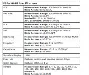
This spec looks like it applies to a 30000count measurement.Here is the spec
Certainly ±0.025% on it's most accurate scale is a very good figure for an "amateur" device.
Andrew
I do not want to go on arguing here - but measurement always requires better accuracy than 0.1% for 1% resistor ( resistance for AC) measurement ( not matching two resistors) here in this thread question is asked why the measurement is not correct.
I would start with better equipment - that is my recommendation
The measurement can never be correct. It will always have a tolerance. The the Builder/Designer has to decide what is "good enough"Andrew
I do not want to go on arguing here - but measurement always requires better accuracy than 0.1% for 1% resistor ( resistance for AC) measurement ( not matching two resistors) here in this thread question is asked why the measurement is not correct.
Yes, better than the supposed error of 13%, would be nice to have.I would start with better equipment .......
Trace where most of that 13% error could come from. It is likely to be an accumulation of a variety of tolerances and errors, not one error.
Using 5% DMM may be good enough.
2% and 1% DMM tolerances could be swamped by the other tolerances.
Does he need to buy a 0.1% DMM to validate his CCS impedance measurement machine?
I would suggest not.
Once he has his impedance method working consistently, would it matter if his error was always in the region of +4% to +4.9%?
He would compare one CCS topology and his error would be consistent between them. He doesn't care if the error is -3%, or +2%, or +5%, as long as the error is consistently in a narrow band to allow effective comparison.
Last edited:
Thanks again for everyone's input.
My 4&1/2 digit bench meter is supposed to be a true RMS meter. The last set of results were taken with an estimate based on the peak to peak level as viewed on the scope then dividing that by 2√2. My two 3&1/2 Digit, actually one is a 3&3/4 digit and the scope all measured the same, so my assumption was that the bench meter was out of calibration. The comparison was made at 50Hz which I can be certain will measure correctly on the 2 handheld DMM's
Udok any amount of expenditure on a new meter is out of the question currently. I think that I may try building a peak detector and measuring the DC output, unless anyone has any better suggestions.
Gordon.
rms voltmeters generally have a much more complex measurement method, but these too are limited to a usable frequency range. My 50000count bench DMM claims to work to ~1MHz. But I don't send it away to be recalibrated and have no way I can check it.
I do occasionally compare my 4 DMMs to see how close they read.
My 4&1/2 digit bench meter is supposed to be a true RMS meter. The last set of results were taken with an estimate based on the peak to peak level as viewed on the scope then dividing that by 2√2. My two 3&1/2 Digit, actually one is a 3&3/4 digit and the scope all measured the same, so my assumption was that the bench meter was out of calibration. The comparison was made at 50Hz which I can be certain will measure correctly on the 2 handheld DMM's
Udok any amount of expenditure on a new meter is out of the question currently. I think that I may try building a peak detector and measuring the DC output, unless anyone has any better suggestions.
Gordon.
The measurement can never be correct. It will always have a tolerance. The the Builder/Designer has to decide what is "good enough"Yes, better than the supposed error of 13%, would be nice to have.
Trace where most of that 13% error could come from. It is likely to be an accumulation of a variety of tolerances and errors, not one error.
Using 5% DMM may be good enough.
2% and 1% DMM tolerances could be swamped by the other tolerances.
Does he need to buy a 0.1% DMM to validate his CCS impedance measurement machine?
I would suggest not.
Once he has his impedance method working consistently, would it matter if his error was always in the region of +4% to +4.9%?
He would compare one CCS topology and his error would be consistent between them. He doesn't care if the error is -3%, or +2%, or +5%, as long as the error is consistently in a narrow band to allow effective comparison.
Thank you Andrew you are clearly a fellow canny Scot, who prefers to find a solution that avoids unnecessary expenditure! 😀
I am going to repeat the 2M2||3.4p measurement with my 3 DMM's and compare with the theoretical value....Bugger that means complex number arithmetic! Oh joy!
Thanks again for everyone's input. For future reference I am on a shoestring budget so preferably I would like as close to zero expenditure, bearing in mind that I do have a sizeable collection of components, that I've built up over several years. 🙂
EDIT: I will also try measuring with a peak detector.
I do have some 0.1% resistors as well which could aid in calibration of my setup.
Gordon.
Last edited:
The meter you use doesn't actually matter: pseudo-rms, rms, average, peak, everything is suitable provided you use the same meter (or at least the same category of meter) for the stimulus and the output
The meter you use doesn't actually matter: pseudo-rms, rms, average, peak, everything is suitable provided you use the same meter (or at least the same category of meter) for the stimulus and the output
Of course as it's a ratio of two voltages!
I do want to find out how out of callibration my equipment is though.
Just a quick round up of my latest efforts. I have identified a number of issues with the most recent setup that have introduced error, notably:
1. Noise and interference getting into the amplifier:
(i) From the power supply via the -ve supply rail.
(ii) From some of the AC test signal again, via the -ve supply rail.
2. Significant DC offset at the output of the amplifier, which has been traced to:
(i) DC leakage in the electrolytic capacitor that couples the current sensing resistor to the amplifier.
(ii) DC across the input resistor due to the input bias current that in itself is small but multiplied by 1600 becomes a problem.
I have more or less come up with a revised setup that should hopefully get round all of these issues, in addition I intend to measure the gain of my amplifier so that an exact figure can be plugged into the formula for determining Z.
It will probably be Tuesday before I get a chance to put all this into action as it is a public holiday tomorrow and I'll be going on a family outing.
Gordon.
Last edited:
- Status
- Not open for further replies.
- Home
- Amplifiers
- Solid State
- How do you calculate impedance of a current source?