I forgot to mention that the <3300Hz impedance was around 3.3Megohms. This is based on an estimate of the output voltage using an oscilloscope as the meter wouldn't settle due to the signal riding on the aforementioned 0.4 Hz signal component. It seems plausible, though its lower than measurements using the first two techniques.
For the time being I've given up on the notion of calculating DC resistance as my intended use for said CCS' is as active loads in audio amplifier circuitry.
Gordon.
For the time being I've given up on the notion of calculating DC resistance as my intended use for said CCS' is as active loads in audio amplifier circuitry.
Gordon.
Often the CCS is not the limiting element in an audio amplifier. The load (e.g. emitter follower) has typically a (much) lower Z
Linearity of the Z is important too. Nonlinear C_CB is a problem for a highly linear gain stage.
It is not easy to build a very high Z circuit. PCB contaminations (no-clean solder paste) and stray capacitance lower the Z considerably (Keithley has a good ebook on measuring low currents).
You can learn a lot by reading the threads about building discrete opamps. Up to now i don't know of a better than average AD797 build. The AD797 depends on very high Z of the single gain stage and that is difficult to realize discrete.
Anyway it would be great if you can test different transistors to see which one are best suited for a CCS. Can you make a table to compare transistors?
Udo
Last edited:
Often the CCS is not the limiting element in an audio amplifier. The load (e.g. emitter follower) has typically a (much) lower Z
Linearity of the Z is important too. Nonlinear C_CB is a problem for a highly linear gain stage.
It is not easy to build a very high Z circuit. PCB contaminations (no-clean solder paste) and stray capacitance lower the Z considerably (Keithley has a good ebook on measuring low currents).
You can learn a lot by reading the threads about building discrete opamps. Up to now i don't know of a better than average AD797 build. The AD797 depends on very high Z of the single gain stage and that is difficult to realize discrete.
Anyway it would be great if you can test different transistors to see which one are best suited for a CCS. Can you make a table to compare transistors?
Udo
Yes, that was always the plan. One other question, for the purposes of drawing up a comparison chart which test frequency should I choose, 1KHz?
I'm still in the dark about what might be causing the 0.4Hz signal.
Is non linear c_cb due to variations in base width, that's just a guess I have no idea what causes it?
Gordon.
Last edited:
Hi,
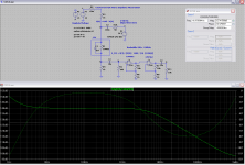
Build the attached Circuit. It will help you to verify your test setup.
I have plotted the frequency response of the CCS impedance.
If your measurement setup is ok, the result should be the identical +-5%.
I have no clue where the 0.4 Hz comes from...
Greetings,
Udo
EDIT: in the formula for Z_CCS: replace V(3) with [V(3) * 1000/1050]
Attachments
Typically in the range of thermal effects. Could your breathing rythm be like 24/minute?I'm still in the dark about what might be causing the 0.4Hz signal.
Typically in the range of thermal effects. Could your breathing rythm be like 24/minute?
Possibly, I'd have assumed that thermal inertia would have ironed out temperature variations this fast. I guess that assumption needs to be reconsidered!
Udo, I will try your circuit but don't have the opamps would an lm833 be a suitable alternative. Are there any particular characteristics that made you choose those opamps?
Your circuit operates at approx 20KHz, do you suggest that I do the same or measure and record Z at various audio frequencies?
Gordon.
Last edited:
LM833 is ok. LM4562 has more bandwidth. Both are good up to 20k.
Measure the impedance at a few frequencies (200Hz, 2k 20k) and see if you can
calculate the CCS impedance correctly.
Maybe a shielded housing (cookie box) helps with the hum/noise problem.
Udo
Measure the impedance at a few frequencies (200Hz, 2k 20k) and see if you can
calculate the CCS impedance correctly.
Maybe a shielded housing (cookie box) helps with the hum/noise problem.
Udo
Your instrument is measuring the change in current through R4.
R4 is not the load, R2 is the load.
R4 passes the R2 load current plus whatever passes through R1/T1
If you use the complementary CCS, then the load can be connected to your ground reference and the load current change can be measured independent of the T1 current.
R4 is not the load, R2 is the load.
R4 passes the R2 load current plus whatever passes through R1/T1
If you use the complementary CCS, then the load can be connected to your ground reference and the load current change can be measured independent of the T1 current.
Your instrument is measuring the change in current through R4.
R4 is not the load, R2 is the load.
R4 passes the R2 load current plus whatever passes through R1/T1
If you use the complementary CCS, then the load can be connected to your ground reference and the load current change can be measured independent of the T1 current.
At first I thought that too. However the current through R1 and T1 is only DC so is blocked by C5. So as far as ac currents are concerned the current in R2 and R4 are the same.
Gordon.
This morning I built the circuit suggested by Udo, though using an ne5534 for the first opamp and a tl071 for the second. After a bit of time wasted tracing a couple of stupid mistakes I'd made with the construction, I was able to determine some useful results. As the measurements taken were not done in exactly the same way, its not possible to make a direct comparison between this method and my last method.
It is apparent though that today's results show relatively higher impedances in the same 2 transistor CCS than in my last method but closer to my first set of results.
Experiment conditions: Vs = +/- 15 volts, I/p signal 2.0 volts RMS. Note that the bottom end of R5 was returned to the -15 volt rail to ensure maximum DC voltage across the CCS under test, CCS DC current = 5.3mA.
RESULTS:
FREQ. Zccs
200. 6.19M
2000. 6.06M
5000. 4.37M
10000. 2.53M
20000. 1.39M
I am going to try setting up a further set of measurements with the same DC and I/p signal conditions as my first method to see how closely the two methods compare.
Would anyone else be interested in carrying out their own set of measurements on the same CCS? Elvee, what about doing a set of measurements using your transformer method.
If anyone is interested, I suggest the following criteria: 20 volts DC across the CCS, 1 V RMS sinewave input signal. Take measurements at; 100, 330, 1000, 3300, 10000 & 20000Hz.
Gordon.🙂
Last edited:
Hi Gordon,
Great to see first results 🙂
Could you verify the measurement setup with the 10 MOhm || 3p3 test?
Udo
Great to see first results 🙂
Could you verify the measurement setup with the 10 MOhm || 3p3 test?
Udo
Hi Gordon,
Great to see first results 🙂
Could you verify the measurement setup with the 10 MOhm || 3p3 test?
Udo
Yes I will try this.
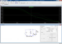
I have attached a schematic of the setup, including an RC power supply filter and another couple of minor variations.
Will post more results later.
Gordon.
Attachments

The latest results using the setup in post #173
Vs = +/- 15 volts, approx -/- 14 v after RC filters.
DC conditions: Vccs = ~18 volts, Iccs = 5.3mA.
Input signal: 1 V RMS sinewave. Signal Gen o/p Z = 50R.
Test Freq. Zccs
50. 6.00M
75. 6.05M
100. 5.30M
200. 5.30M
330. 5.30M
1000. 5.30M
2000. 5.30M
3300. 4.99M
5000. 4.24M
10000. 2.65M
20000. 1.60M.
Gordon.
The figures for 50 & 75 Hz were again estimates using the 'scope as the bench meter wouldn't settle at these frequencies.
Last edited:
I made the test; I first checked the calibration with 1Meg and 10Meg resistors, and it was within a few % (resistors are 5% tol.)Would anyone else be interested in carrying out their own set of measurements on the same CCS? Elvee, what about doing a set of measurements using your transformer method.
If anyone is interested, I suggest the following criteria: 20 volts DC across the CCS, 1 V RMS sinewave input signal. Take measurements at; 100, 330, 1000, 3300, 10000 & 20000Hz.
Code:
[U]Freq. (Hz)[/U]   [U] Z (MΩ)[/U]

   100         28.5
   330         16.6
   1K          14.2
   3.3K        11.7
   10K         6.25
20K 3.3The resistive part of the impedance must be around ~30MΩ, and the capacitive component kicks in at ~1KHz and dominates completely above ~5KHz: the ratio of 10 to 20KHz is almost exactly 0.5
I checked with BC550C's from Philips, I get 11.8MΩ @1KHz
My transistors were cheap and nasty 2n3904s from China, will need to try a CCS with some decent transistors, I do have some in the midst of my massive collection!
Thanks for sharing your results Elvee.
Gordon.
Have just spent a very frustrating evening having realized that my set up was out by about 10% when checked with a known resistor value. It turns out that the bench meter was out by around 10% compared with the two small DMM's and the 'scope. Problem with the two small meters is that they can only manage to measure ac up to 1KHz, so that just leaves the oscilloscope. In fact the results using the scope were not bad actually.
For a 2.19M test resistor ( measured with my peak electronics LCR meter ) my setup measured 2.15M between 50-20000Hz. Not bad at all. 🙂
Next test was the same resistor in parallel with a 3.4p capacitor again measured with the LCR meter.
Results:
50: 2.15M, 100: 2.15M, 330: 2.15M, 500: 2.15M, 1000: 2.15M, 3300: 2.07M, 5000: 1.99M, 10000: 1.71M, 20000: 1.38M
More results to follow soon.
Gordon.
- Status
- Not open for further replies.
- Home
- Amplifiers
- Solid State
- How do you calculate impedance of a current source?