I've seen a few DAC designs that run a 12VDC rail around the board to 3V3 and 5V regulators at each pin requiring power but the datasheet's I've been looking at are recommending a common decoupled supply.
Cheap asian stuff , that second low noise buffer (in wenzel's
articles) is in the mars rover !
"Alien tech" for our DAC (Wenzel tech).
The site also has articles on ZERO jitter space tech oscillators ! oooooH!
OS
Cool. I've been looking for a clock design. I've been looking for USB I2S designs as well. That looks like a bit of a pain too.
Cool. I've been looking for a clock design. I've been looking for USB I2S designs as well. That looks like a bit of a pain too.
Yes, clocks are also a audiophool "fetish" type circuit ...silver inductors ,
rubidium oscillators (wow - atomic clocks).
Some swear that accuracy = SQ
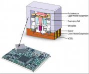
Some will install a "physics package" (below) -10mhz rubidium and swear
by its "fidelity".
Thats "toplevel" stuff.
Next down is temperature stabilized crystals (TXCO's).
Then , what we use on the arduino - "plain ol' crystal".... 😱😱
OS
Attachments
Yes, clocks are also a audiophool "fetish" type circuit ...silver inductors ,
rubidium oscillators (wow - atomic clocks).
Some swear that accuracy = SQ
Some will install a "physics package" (below) -10mhz rubidium and swear
by its "fidelity".
Thats "toplevel" stuff.
Next down is temperature stabilized crystals (TXCO's).
Then , what we use on the arduino - "plain ol' crystal".... 😱😱
OS
I'm thinking a simple crystal buffer would likely fix the jitter enough.
i read the finesse app years ago but never used those ckts yet.
just like a transformer does. when you get noise levels below the hum, then hum is the dominate noise source. unless the hum source is far away.
once you get to your layout you will have to decide the optimum place to connect the 2 ground systems together!!
if you are distributing a supply with ac ripple, it can radiate into sensitive circuits.Lower PSRR won't be a problem for digital ...
just like a transformer does. when you get noise levels below the hum, then hum is the dominate noise source. unless the hum source is far away.
then why use it, you know that a larger transformer will probably create a large mag field thus radiated hum?Edit - as far as relay load / digital load ... that 2'nd 18V secondary is 2A !
I can't foresee even using 1/4 of that.
once you get to your layout you will have to decide the optimum place to connect the 2 ground systems together!!
i read the finesse app years ago but never used those ckts yet.
if you are distributing a supply with ac ripple, it can radiate into sensitive circuits.
just like a transformer does. when you get noise levels below the hum, then hum is the dominate noise source. unless the hum source is far away.
then why use it, you know that a larger transformer will probably create a large mag field thus radiated hum?
once you get to your layout you will have to decide the optimum place to connect the 2 ground systems together!!
You are my "conscience" (like the cricket 😀) , Rsavas ...
For this - my 200VA will fit in a shielded can. Why create anal supplies
just to have a big EMI (field) sitting beside them ?
I'll use the 18V ... because it's there ? Most of these DIY/IC regs will
"like" the 25V unregulated input.
I know the trafo is oversized (8" logitec sub trafo) , but it is free !
PS - the -72db plus the 20db from the shunt will give me -92db PSSR
for the 5V supply. Regulate off of that for the 3V3 will give even
more. By "less" PSSR , I meant not as good as the Jung's @ 125+.
OS
The part has a PVDD/PGND which needs a very clean supply.
The PLL and master clock ckts require a clean supplies, as supply noise creates jitter in the data. Some apps just use a ferrite/choke, off of the dirty supply, but better designs would use a small LN reg or one of those finesse NR ckts.
DVDD/DGND are the logic supply so they can be dirty.
Look at the eval design and follow that.
Interesting Wolfson is now part of Cirrus Logic and cs8416 discontinued, replaced with wm8805
The part has a PVDD/PGND which needs a very clean supply.
The PLL and master clock ckts require a clean supplies, as supply noise creates jitter in the data. Some apps just use a ferrite/choke, off of the dirty supply, but better designs would use a small LN reg or one of those finesse NR ckts.
DVDD/DGND are the logic supply so they can be dirty.
Look at the eval design and follow that.
Interesting Wolfson is now part of Cirrus Logic and cs8416 discontinued, replaced with wm8805
I'll Make the PVDD/PGND supply as a common mode choke (CLC) , then the 317-shunt.
I saw this on some precision raspberry pi DIY supplies. Raspberry Pi Power Supply
It should match the analog in precision.
The CM inductor , lm317 , and shunt can all be SMT. I'll post the sim
results for both pssr/noise when I decide on the final hybrid.
It should be way above average in performance.
OS
The part has a PVDD/PGND which needs a very clean supply.
The PLL and master clock ckts require a clean supplies, as supply noise creates jitter in the data. Some apps just use a ferrite/choke, off of the dirty supply, but better designs would use a small LN reg or one of those finesse NR ckts.
DVDD/DGND are the logic supply so they can be dirty.
Look at the eval design and follow that.
Interesting Wolfson is now part of Cirrus Logic and cs8416 discontinued, replaced with wm8805
I've always used evaluation designs. Let the IC designer figure out how to make his product work.
I'll Make the PVDD/PGND supply as a common mode choke (CLC) , then the 317-shunt.
I saw this on some precision raspberry pi DIY supplies. Raspberry Pi Power Supply
It should match the analog in precision.
The CM inductor , lm317 , and shunt can all be SMT. I'll post the sim
results for both pssr/noise when I decide on the final hybrid.
It should be way above average in performance.
OS
Do you want to place these regulators locally, near the ICs themselves? Will the choke emit any noise worth worrying about?
I do need separate 3V3 supplies for this one.
Typical of a digital transceiver ? Built in TXCO , as well.
I suppose this leaves a precision clock for just the DAC.
(no rubidium 😀😀 ) .... or maybe , with an external input.
OXCO's are 1X10 -12 stable (better than a txco) and cheap , as well.
OS
Typical of a digital transceiver ? Built in TXCO , as well.
I suppose this leaves a precision clock for just the DAC.
(no rubidium 😀😀 ) .... or maybe , with an external input.
OXCO's are 1X10 -12 stable (better than a txco) and cheap , as well.
OS
The DAC runs off the clock in the SPDif decoder so they are synchronized. If I figure out a USB circuit I like it I will need to switch the clock circuits with the inputs.
Do you want to place these regulators locally, near the ICs themselves? Will the choke emit any noise worth worrying about?
Yes , local .... The common mode choke won't be like a amp inductor. It's
core will just absorb the EMI/RFI before it enters the regulator. No big
AC inductive coupling like in a power amp. Cleans up the ground reference , too.
So , it will do the opposite ... absorb instead of emit.
This , on top of the bigger choke at the mains input - no garbage.
How local ? ..... same board , does not have to be "right on" the chip (like a
decoupling cap).
OS
chirp chrip
TXCO ? what 🙂 how about TCXO, OCXO (oven controlled xtal oscillator)
Do not mix up clock jitter with accuracy and drift!!
If you notice in the Wolfson WM880x evals, they use a separate, off board, PVDD!!
I do not know about using a CM choke for PVDD. You are going to route the return from PGND pin through the CM choke to digital ground?
i"d use a choke(L/C) off of the 5V,LN 3V3 lin reg to PVDD. tie DGND & PGND to your ground plane.
Last edited:
Yes , my cricket ! 😀
I'm digesting this - http://www.sitime.com/support2/documents/AN10007-Jitter-and-measurement.pdf
I'll have the "jitters" down.
Thanks for "conscience" !
OS
I'm digesting this - http://www.sitime.com/support2/documents/AN10007-Jitter-and-measurement.pdf
I'll have the "jitters" down.
Thanks for "conscience" !
OS
Here is a suggestion for a LN supply for WM8803 and other similar devices.
http://www.ti.com/lit/ds/snvs358q/snvs358q.pdf
WSON package is not too bad to work with, esp if you reflow.
http://www.ti.com/lit/ds/snvs358q/snvs358q.pdf
WSON package is not too bad to work with, esp if you reflow.
What about MIC5205 for LN supply, it SOT-23-5, still manageable by hand ?
I was about to mention that ! NO oven/reflow stuff (soldering iron only).
The MIC specs at 260nV/hz noise ... just 100nV under a LM317. 🙁
They describe this as "low noise" ??
The finesse shunt can do 20-50nV/hz !
If the low noise is truly worth it , perhaps a scaled down version of a mini IC
regulator/shunt could be implemented (where required).
I now have read on the "jitters" ... some are caused by noise ,some by
regulation/ripple.
The finesse shunt is cool ! Just amplifies the noise and applies a inverse
shunt to the output. Most regulator IC's are just series pass with a error
amp - you get all the noise of the series device at output.
The series /shunt combo is the "cats meow" for a low noise digital PS.
PS - If there is an IC combo like this , let me know !
OS
431 reference as shunt
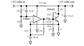
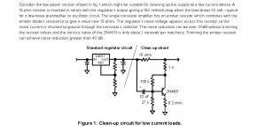
This noise reduction method is better (easy). It integrates
most of wenzel's ultra shunt into one little package.
At <200nV/hz , not bad .... but still not close to wenzel's
last op-amp shunt circuit (below 1= <20nv/hz).
Finding a op-amp to work on 5.5V might be problematic , so
just the simple one BJT shunt (below 2) still gives <100nv/hz.
So , just a LM317 (emp) sot232 IC plus another smd BJT (and a few caps/
resistors) gives at least twice the performance as the standard IC
shunt.
I guess where you use this tech depends on how sensitive the digital
IC is to the noise ??
This is definitely something for the "toolbox" that allows for above
average designs !
PS - three "levels" ....
TL431 = 200nV
(below 2) = <100nV
(below 1) = <20nV
OS
Attachments
- Home
- Source & Line
- Analog Line Level
- Pitchfork pre-amplifier