Schema 1 seems to have a digital and a analog side to the IC. (pcm1794).
Looks like the analog side can just be regulated off one of schema 2's op-amp
supplies.
Schema 2 ... just the buffers/IV , use the jung supplies.
The digital 3.3V side of the 1794 and the 8804 can be a standard
LM732 circuit with the clean-up wenzel shunt in front of it.
OS
Looks like the analog side can just be regulated off one of schema 2's op-amp
supplies.
Schema 2 ... just the buffers/IV , use the jung supplies.
The digital 3.3V side of the 1794 and the 8804 can be a standard
LM732 circuit with the clean-up wenzel shunt in front of it.
OS
Look at this transciever... 8804 based , but with a 3- state digital buffer added
to get them neato dual color LED status indicators (lock , error , non-audio).
http://www.twistedpearaudio.com/docs/digital/wm8804_schematic.pdf
The S/PDIF Transceiver Module
He also uses local LP2985 regs to buffer the Pvdd. Vcc would be a global ,
more powerful 5V regulator (like my shunted one).
OS
Schema 1 seems to have a digital and a analog side to the IC. (pcm1794).
Looks like the analog side can just be regulated off one of schema 2's op-amp
supplies.
Schema 2 ... just the buffers/IV , use the jung supplies.
The digital 3.3V side of the 1794 and the 8804 can be a standard
LM732 circuit with the clean-up wenzel shunt in front of it.
OS
If we go with a PGA2311 pot it will need +-5V for analogue too. I assume it would have a more suitable output to the output buffer than PGA2310?
Look at this transciever... 8804 based , but with a 3- state digital buffer added
to get them neato dual color LED status indicators (lock , error , non-audio).
http://www.twistedpearaudio.com/docs/digital/wm8804_schematic.pdf
The S/PDIF Transceiver Module
He also uses local LP2985 regs to buffer the Pvdd. Vcc would be a global ,
more powerful 5V regulator (like my shunted one).
OS
We could add more blinking lights if you like.😀
If we go with a PGA2311 pot it will need +-5V for analogue too. I assume it would have a more suitable output to the output buffer than PGA2310?
I thought the 1794 only needs +5 ?..that's why it runs its analog outs to a differential. (Vcc2- L/R)
They call for a +5V "analog supply" , but do they mean run it off of a separate
supply ?
The pga2311's +/- 5 V would be the best candidate for locally buffered
supplies run off the Jung's (main buffer supply). It's the first analog "upstream"
from the main buffer.
OS
We could add more blinking lights if you like.😀
Even the "pocket dac" has a "lock" indicator. 🙄
Some will tell you whether you are 44/96/192khz data rate , as well.
OS
I thought the 1794 only needs +5 ?..that's why it runs its analog outs to a differential. (Vcc2- L/R)
They call for a +5V "analog supply" , but do they mean run it off of a separate
supply ?
The pga2311's +/- 5 V would be the best candidate for locally buffered
supplies run off the Jung's (main buffer supply). It's the first analog "upstream"
from the main buffer.
OS
The analogue side of the PGA1794 runs on +5 and ground. The digital side is +3.3. I would assume the analogue would be separate very clean supply.
Even the "pocket dac" has a "lock" indicator. 🙄
Some will tell you whether you are 44/96/192khz data rate , as well.
OS
If I have audio I assume it has lock and is working. I'll add the LEDs for those who like them though.
The analogue side of the PGA1794 runs on +5 and ground. The digital side is +3.3. I would assume the analogue would be separate very clean supply.
Twisted pear - http://www.twistedpearaudio.com/docs/linestages/legato_3.1_schematic.pdf
separate modules and PS's for everything. Look how the headphones are
implemented on the LME49600. A 22R going to the output. Gain of buffer is changed for the headphones.
So , two supplies for all the digital ... one for the 1794's analog.
A 5V /5V / 3V3 with all the regs running off a 14V unregulated supply.
Then , the Jung +/- 15V supplies can run the analog 5 and 15V requirements
on all the boards.
OS
I'm having trouble making any sense out of that schematic. Where are the headphones fed from and why is there a switch shorting the outputs to ground?Twisted pear - http://www.twistedpearaudio.com/docs/linestages/legato_3.1_schematic.pdf
separate modules and PS's for everything. Look how the headphones are
implemented on the LME49600. A 22R going to the output. Gain of buffer is changed for the headphones.
So , two supplies for all the digital ... one for the 1794's analog.
A 5V /5V / 3V3 with all the regs running off a 14V unregulated supply.
Then , the Jung +/- 15V supplies can run the analog 5 and 15V requirements
on all the boards.
OS
Dadod's MK2 used different resistors on the output for line out and headphones.
Do we need a totally separate 5V supply for the DAC or could it be fed off the Jung as well?
I'm having trouble making any sense out of that schematic. Where are the headphones fed from and why is there a switch shorting the outputs to ground?
Dadod's MK2 used different resistors on the output for line out and headphones.
Do we need a totally separate 5V supply for the DAC or could it be fed off the Jung as well?
I see what you mean , he shorts out the LME buffer and derives
the headphone output from the discrete I/V stage ??
Since the 5 and 3V3 digital will be virtually unloaded (my 14V puts out
2 amps ! ) Why not take the DAC analog from it as well with a separate
regulator ?
All the digital circuits (PCM/PGA/8804) will just draw >150ma !
If you add led's , maybe 200ma max.
Could be almost battery powered ....
OS
suggest to have the option of using the spi i/f on the wm8804 and connect up to the mcu spi bus. Use the same bus as pga23xx. it can be 3v3 as pga23xx is ttl compatable, 2V v hi min.
I have to look at wm8804 to see if it uses a slave select, so all you need is a slave select control bit for pga23xx and wm8804.
pga2310/20 goes down to +/-5V, i have tested this. Can be powered by option of +/- 5V to +/- 15V, jumper selectable. The ? is how much dynamic range do you want. you are going to want +/-15V for I/V opamps and other stuff as it is.
the analog 5V for DAC should be derived from a non-digital supply!!
That is good OS, document your power budget in a spreadsheet, typ vs worst case max, like a good EE should do 🙂
Okay back to body work on the old 95 chev 4x4, out on a friends farm.
Cheers
Rick
Last edited:
As there is a lot of discussion on shunts here and the Jung regulator someone mentioned to me at some point that the Jung could be made into a shunt supply...was that considered?
1-
suggest to have the option of using the spi i/f on the wm8804 and connect up to the mcu spi bus. Use the same bus as pga23xx.
2-the analog 5V for DAC should be derived from a non-digital supply!!
Rick
Rsavas .....
Some questions -
1- by using the same bus on the 8804 and the pga , why ? To synchronize
them if they are to micro controlled ?
2- The analog 5V .... It just has to have it's own regulator ? Can I operate
this regulator from the same unregulated supply that I derive the digital
from ?
Or do I have to regulate one of the analog supplies down to 5 V ?
OS
As there is a lot of discussion on shunts here and the Jung regulator someone mentioned to me at some point that the Jung could be made into a shunt supply...was that considered?
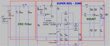
Besides burning up wattage , why use a shunt on the jung ?
It only has 100nV noise. (below) ... if you combine the Wenzel shunt
with the jung , you get 3db more pssr and reduce the noise to the
BC550's and R17's noise (shunt section - below).
The combo seems just as "bad" as just the series regulator ... same
15.082V , as I referenced the output after the resistor to the error amp.
Shunting between 25 and 100ma gives 2nV noise !!
OS
Attachments
using the spi bus connected to the wm8804, you can access all the status registers and have full control over hardware control. the bus spi bus can be shared to save on mcu pins.1- by using the same bus on the 8804 and the pga , why ? To synchronize
them if they are to micro controlled ?
yes it's own regulator or a shared 5V but from the analog transformer instead of the digital transformer, assuming you have both, if not then if only one transformer, isolate/filter/regulate the best you can. There is both analog and digital grounds on most DACs.2- The analog 5V .... It just has to have it's own regulator ? Can I operate
this regulator from the same unregulated supply that I derive the digital
from ?
Or do I have to regulate one of the analog supplies down to 5 V ?
Last edited:
Thanks for the reply OS, Just had always wondered about the performance of the Jung as a shunt. At one point I was looking a supply to power a THAT 1206 balun. line receiver and someone gave this as an option. But now I know and perhaps I too will look at the wenzel.
http://www.diyaudio.com/forums/power-supplies/238903-good-regulator-7-8ma-load.html
http://waltjung.org/PDFs/AX_WJ_Interview.pdf
http://www.diyaudio.com/forums/power-supplies/238903-good-regulator-7-8ma-load.html
http://waltjung.org/PDFs/AX_WJ_Interview.pdf
The combo seems just as "bad" as just the series regulator ... same
15.082V , as I referenced the output after the resistor to the error amp.
Shunting between 25 and 100ma gives 2nV noise !!
OS
What's the hit on the Zo spec though?
What's the hit on the Zo spec though?
Yes , no longer ideal (@ milliohms).
I'm just extrapolating this conclusion because I can't get a Z out plot 🙁😱 .
R17 for DC/LF and the output decoupling cap for AC-HF ( 2-3R Z).
I tried the forum search for the method , still just get db.
I'm only using the low noise shunt for low current digital , do I need
real low Z ?
.ASC below ... could some help to plot the Z ?
OS
Attachments
Depends on priorities. Noise spec vs dynamic spec. To sacrifice mOhm spec for several Ohm spec takes some serious application specific reasoning. If the particular device (load) changes some current draw then the high Z regulator's output will modulate along accordingly. Test the device to see if its constant draw or not first.
Can't run your .asc because my LTspice is set on different component libs but If you can already produce Zo dB over AC for out then right click on V(out) curve title and make it V(out)/1A also left click just beyond y axis where a ruler symbol shows up, select linear presentation and the plot range settings also, like in this example:
Can't run your .asc because my LTspice is set on different component libs but If you can already produce Zo dB over AC for out then right click on V(out) curve title and make it V(out)/1A also left click just beyond y axis where a ruler symbol shows up, select linear presentation and the plot range settings also, like in this example:
- Home
- Source & Line
- Analog Line Level
- Pitchfork pre-amplifier