Thanks, Ryan...I've been playing around with LTspice. Here is what i've found, its fairly self explanatory.
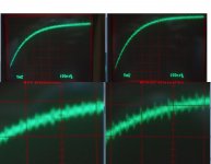
Blue trace is the signal coming out of i2s to pcm PCB.
Green trace is without the 22R - R3
Red trace is with R3
The Red trace looks a lot slower but is in fact ~700ps
I think this may be worth trying.
Ryan
Could you please post the parameters of the first voltage-source, so I can also play around with the circuit? unfortunately that part is left-out in the screendump...
Thanks in advance,
Edwin
Hi Edwin,Thanks, Ryan...
Could you please post the parameters of the first voltage-source, so I can also play around with the circuit? unfortunately that part is left-out in the screendump...
Thanks in advance,
Edwin
Here you go:
PULSE(0 3.3 10ns 1ns 1ns 30ns 30ns 1)
The logic Ians board uses has a rise time of 800ps. I measured about ~2ns, but this could have been impeded due to ground clip type. So in the simulation i put 1ns - should get us in the ball park.
Cheers
Ryan,
Having a close look at the board I see than the -15V has two different decoupling in relation to the grounds : I have a doubt !
there is a smt trace for a ddecoupling to the bottom analog (AGND) star ground but also a main decoupling with the via/hole main cap on both bottom and upper digital plane ground (DGND)! Is this not creating a huge ground loop ?
Is it normal or an error of printing/layout (a basic non understanding from me) ?
If an error : better to have a - 15V referenced to the analog or digital groundplane first ? (but not both I mean !)
It would be better (?) :
1- just use one of the two decoupling possibility : first the smt trace as :
- it's analog ground and pin5 AGND is tied to upper DGND upper plane : longer decoupling but first analog ?
- with 1 uF smt decoupling cap e.g. (PPS, acrylic) this value is enough as most of us uses shunt reg/stabilasation for PS !
2- just use the main cap decoupling avoiding the smt trace for decoupling (which is enough with all the good caps : BG, polymers...
3- or cut an island around the main cap via/hole Gnd on the upper plane isolate it from the upper plane and on the bottom plane : cut an island around the gnd via/hole to trace a path on the beginning of the smt analog decoupling trace to isolate the hole/via from the bottom digital gnd which is closely connecterd to pin 14 (DGND)
I don't remember the dependancies of the 3 voltages rails in relation to the analog part of the ship then digital parts : I know there is a close relation but an order in importance :
- 15 V : very important for the analog
- then - 5 V ?
- + 5V : less important in relation to the analog domain (ground)
Should all the decoupling of the three rails be better firstly on the analog ground or on the digital ground ? And if so : the importance to have a 4 layers with two grounds (digital and analog 2 layers just tied together with a via/hole on the pin 5 (or pin 14 in relation to the current flows ... or eslwhere in the middle of the board) ?
Basicly it could it be better to have if two layers only as now we have with the actul Distinction-1541 V1 : upper plane digital Gnd (DGND), bottom plane : analog ground but still with the central starground to force the DEM caps towards the pin 5 (AGND) and around (of the tda1541) an island made of an analog ground tied on the pin 5 (so always in the bottom of the pcb) but from the opposite side of the TDA (pins row 28 to 15) ?
Could be good if the supplies need to be decoupling on the analog ground first ?! And notice this is at the opposite side of the digital pins (but the upper pin 5)
Hi Damien,
Heres a quote from Henk that may help:
I stated:
Current reference generator for the output current is between -5V and -15V. Output current from the dac comes out of pin 6, 25 via diode switches or comes out via the +5V pin 28 by darlingtons. This means that complementory output signals L+R flow in supply pin 28.
And Pedja responded:
I do not quite figure this. Three or 4 active divider pins are inside -15V- -5V range but the others are not.
Interesting note about pin 28.
Pedja
I made two statements.
1. Current reference generator for the output current is between -5V and -15V.
What was ment here is where the current 'reference' generator circuit is, that it is supplied between the -5V and the -15V pins. With other words, the supply voltage of the current reference is 10V. This current reference is the reference for all binary weigthed currents in the TDA1541(A). The supply rejection ratio for this current reference is not infinite, thus this 10V should be as constant as possible.
The binary weigthed currents in the TDA1541(A) are made accurate by the dem circuit, the voltages on the filters for this dem circuit are not direct related with the supply voltage of the current reference. The fact that (some of) these voltages are above the supply voltage of the current reference is not in conflict with my statement.
2. Output currents from the dac comes out of pin 6, 25 via diode switches or comes out via the +5V pin 28 by darlingtons. This means that complementory output signals L+R flow in supply pin 28.
The inner curcuit of the dac can be seen as a binairy controlled differential stage.
One output (the not used) flows in pin 28, thus +5V. The outher output in pin 6, 25. The sum of signal currents in pin 6, 25 and pin 28 is constant. That means that it is advantageous to bring the output currents in pin 6, 25 back into the +5V supply. That can be done by e.g copying the output current into the +5V supply. If done correct, the signal in the +5V decoupling capacitor completely disapears.
regards,
🙂thanks Ryan for those détails, interresting,
But I can't understand the best way to decouple -15v in relation to the double ground decoupling made :
Should I use the path on the Distinction which go from the smd cap trace to pin 5 (agnd)
Or the DGNG via/hole you made for the main -15v decoupling cap which is connected to the two digital ground (dgnd)
I mean despite what wrote above, one should not use the both at the same time ?
So better to use only the digital via ground for the -15 V as the -5 V is also using a digital via/hole gnd for its main decoupling cap ?
I understand maybe it will be better to ground all the supply on the analog ground first then tied it to the digital ground near the pin 14 instead : in this case the ground loop of pin 15 with analog ground and pin 14 could be very short and its return current not floating between pin 5 and 14 like it is on the actual distinction board if you use the both decoupling possibility of the -15 V traces (via/holes for radial cap & smt trace for smd cap which goes direct to pin 5 by its own path) ?
And as well for a V2 not to allow to pin 5 to be connected to digital ground near the pin 1 to 4 !
Or it's not important at all ? (in relation of what you explain just above ?)
Sorry not clear for me... what would you do yourself : radial cap or smt one or both ?
Not so important, but, let avoid worst possibilities if possible !🙂
regards
Hi Damien,
From what i've read, the -15v supply is indeed important for the analog output, it supplies the DEM for the LSBs, it also forms a current reference generator for the output current between -5V and -15V.
I think it may not be a good idea to use only one ground route or the other, the currents will take the path of least resistance, they won't take the long route to form a loop (higher impedance). My advice would be to use both, but theres nothing wrong with experimenting.
Hello Ryan,
😱
Experiments are important indeed !😀
I should advise to use no caps ! Not on the main vias/hole, and not in the smt traces either for the -15 V on the Distinction! Of course if shunt reg !
I don't see why the higers fhz and most rapid should be decoupled with the smt traces and the small value as this is a // cap on the analog pin with a different impedance than the the slower one (main cap) wich are near pin 14 (DGND) ! It makes simply no sense as they have total different impedance in relation to the frequencies ! Au secour !😕
With a good shunt, the local decoupling is not necessary on the - 15 V, it's how it is with the AYA 2 2014 with my multiple experiments and in the actual state of the Distinction1541, I will not use myself any decoupling on the actual layout of the -15 V in the Distinction and certainly not the both in the same time ! but also the to others rails like the layout is done today !
We should have a different look on the V2, but if all is good like that... Amen !
regards
Ryan, you confirm what I expected about the TDA... PS is of utmost importance if you want to get optimal results. Thanks for your measurements.😎Hi Damien,
From what i've read, the -15v supply is indeed important for the analog output, it supplies the DEM for the LSBs.....
I don't think this matches my ear. I find even with a shunt a good cap as close as possible to -15v pin is a clear improvement in sound. On the Distinction I use an organic polymer plus a good 1u film cap right on the pin. On past TDA1541a DAC and on CDPs I found a blackgate soldered right on the pin close to the IC is best. Try it without first then add the cap. I will be surprised if you do not keep the cap.Hello Ryan,
I should advise to use no caps ! Not on the main vias/hole, and not in the smt traces either for the -15 V on the Distinction! Of course if shunt reg !
But each to their personal preference. Like spice on food. Nothing is right or wrong.
I recall Thorsten said to do the same when using TL431 shunts. He said better regs are possible but self noise of chip makes the TL431 good for most DIY implementations. He also the output impeadance of the TL431 could be improved by putting a large value low esr cap near pins. From memoy 470UF or something. I'm pretty sure he always uses a bypass cap.
I expect if your using a Salas shunt you may want to watch how much capacitance you use after the shunt. I think they don't like capacitive load.
I guess the answer is dependant on the implementation?
I expect if your using a Salas shunt you may want to watch how much capacitance you use after the shunt. I think they don't like capacitive load.
I guess the answer is dependant on the implementation?
Ahhh the old CAPACITOR debate............................
Eldam, use none if thats what you like, as Walter said, its all about personal preference. Sure its not unheard of to use no caps with a shunt reg.
"I don't see why the higers fhz and most rapid should be decoupled with the smt traces and the small value as this is a // cap on the analog pin with a different impedance than the the slower one (main cap) wich are near pin 14 (DGND) ! It makes simply no sense as they have total different impedance in relation to the frequencies ! Au secour !"
If you can't understand that a digital square wave contains harmonics well into the hundreds of mhz... well then I can't help you.
I've got shunt regs and i've tried without local filter caps - For one, an increase in measurable noise using a scope (under a mV, but visible). And of course, two, the sound degraded. It depends on your setup! The shunts i'm using don't have as high frequency response as the caps i'm using - not to say that means it will sound better necessarily. As Jaffrie has suggested, the 1541 may actually prefer a higher impedance on its power supplies.
Use whatever you prefer, this is the whole point of the Distinction-1541 PCB.
Ryan, you confirm what I expected about the TDA... PS is of utmost importance if you want to get optimal results. Thanks for your measurements.😎
You're very welcome, this ancient dac chip is a diyers dream, so many things to play with, and so many different combinations to get the sound you want. 🙂
Right you are. I think it very nearly drove John at ECDESIGNS nuts as he experimented daily for 5 years. It also helps to some extent to be satisfied with what you have and keep experimenting for fun and learning not obsession.
Attenuation update.
Been playing around with the attenuation PCB i made.
Now that i realised that LE - latch enable is triggering the sample to the analog outputs with the offset binary format (simultaneous mode), it occurred to me that i should try to attenuate BCK and the data lines only. (small amount on LE)
DATA L/R: 470R
BCK: 470R
LE: 50R
Please note that this is probably not a desirable setup, just for testing purposes before i make the Diode attenuator.
Attached is a shot of a full scale current sample, the rising edge has a rise time of about 550ns (22nF on the analog outputs)
Notice a 1mV reduction in switching noise with attenuation.
As for how it sounds.... Promising signs - Definitely worth taking it further.
Attachments
Hello Ryan,
I find the experiment you do very interresting but it must not hide the global layout forest other more important problem than a V2 could solve instead focusing on the I2S attenuation tree... this is not like if there is nothing behind the tree. Both can be made if you print a V2..
I permitt myself to say this not as a criticism as I also was one of the main conductor of the Distinction project and I remember also how fast you wanted to close it and take it "Under controll as drawer" despite what was said !
The squarewave has nothing to see with the problem of a splitted way ground I asked and which was according to me an error and idem with the debat caps you through me to the face like if I was a fool or to allow the others to think : "look what he saidd is not important, he is himself on the caps level only" !
To be honnest with you, you can not help me here as this is me who is trying gently to help you and the communauty once again by a humble colaboration and modest hints and question to allow to advance..... that you can see like an opposite of the "all Under controll" maneer your seems to prefer !
I have the AYA 2 2014 pcb Under my eyes and your and some others doozen made by Philips & Marantz ... I believe Pedja Rogic who is the first to use the simultaneous mode knew what to do and I can listen to it everyday ! Whatever the squarewave and I know what harmonics are : I can mistake but we don't want a rapid signal to have two different ground resistive value as reference. Maybe here it's not important with the slow TTL old dac chip but don't forgett some want to use upsampling at the higest fhz tda1541 allow !
Like you said the -15 V is feeding also the DEM cap... and onece again It will be better than the local decoupling cap has only the same path : so with the smt trace you should probably extend it to the main radial decoupling cap round as well.... or like the other does choose pin 14 to be tied directly near the analog ground which is used as common ref for all the supply first to avoid gently pin 5 to be the mix point of DGND and AGND directly on its pin !)
Once again, talking with caps if you want : a good developped shunt stabiliser doesn't necessarly need a local decoupling at the end as this is the caps before who are giving the energy and must have a very low esr. If a local cap is needing and yes it is better most of the time, few nano is only needed and you must care to avoid oscilations i regard to the design: 0.2 to 1 uF is enough most of the time !
Here my remark came from what I experiment with caps on the AYA2 2014 which have a good shunt on the same pcb the closest it is possible to the chip. And this is not magical but technical and known : I can hear difference when BG N (which is a bipolar with a long and short leads because it has a sense ! Here it was better to me without on the -15V rail in this particular conf with a special arrengement of BG on the -/+ 5V rails with the same attention on the orientation of the leads ! So no ********, a kid can hear the difference ! I didn't said it is better using no caps but said in this particular layout error you draw (maybe I'm wrong and as we copied John I'm going to ask him myself instead staying in the doubt or error !))
As my humble advice : your actual Salas shunt is not made for feeding a dac chip but an analog stage, certainly not a big large enough bandwidth for it ! Use a reflektor D if you like Salas shunts ! But you should not experiment and have final conclusion with your actual supllies !
But if you want to keep this work as only yours and keep it for a V2 .... what can I say ? Nothing ! You made also great effort to draw, to print and to share with the "team". Here I just wanted only help as usual ! BTW I'm going to ask John about this splitted ground as the Distinction is mainly an athorised copy of him work with some trade offs choosed (no attenuation, no external dem clock layout, etc) !
We should had listen more T. Loesch advices about layout....
kind regards
Is this DIY or TSEHTDI? (tell someone else how to do it). Let us experiment with the actual builds and we will all have fun and learn.
Wolwes WTF, you were not here to help us when we did this board, so your comment is irrevelant !
It's not about what you are saying above, everybody is free but it was also a grup project first !
So keep your moral please, it's not like if you contribute as I did in this project !
So yes you are free to experiment and I stay free to ask what I want and Ryan is free to answer alone, we are both big boys!
And mostly you can enjoy this board because we already had a lot of exchanges between Ryan and me and some others, and perfectly friendly, we can not agree sometimes, but we stay on the same side of the force to speak about moral, ethic or whatever !
regards
Last edited:
To quote my lifelong spiritual advisor, Crocodile Dundee..." That's not a harangue...THIS is a harangue ! " 
Bah ....if you can follow things it's an harengue as answer to an other harangue😀.
But this is not like if the words have no sense nor the situation it has to solve ! One can be short with words, but often give a poor thought ! mostly when it's not your native language !
You can look at whatever movies you like, but this board was not made from simple sentences 😉, it came from a long collaboration during few months !
A Big Lebowski could say: " Don't **** on my carpet !"

- Status
- Not open for further replies.
- Home
- Source & Line
- Digital Line Level
- Group buy/Interest list - TDA1541A Core board.