Well yes, there are various reasons why one would use these types of valves but sure enough one could make a series reg with an EL84/6BQ5 and a ECC83 as an error amp as well.
This would be an ideal setup for my needs I believe.
Hi,
This one is actually a shunt regulator but it does what you want to achieve:
Aikido PCB & Broskie OTL & Feesforward Shunt Regulator updates
Keep in mind that if you click on "Next" you actually arrive at the previous article.
Cheers, 😉
This one is actually a shunt regulator but it does what you want to achieve:
Aikido PCB & Broskie OTL & Feesforward Shunt Regulator updates
Keep in mind that if you click on "Next" you actually arrive at the previous article.
Cheers, 😉
Hi,
This one is actually a shunt regulator but it does what you want to achieve:
Aikido PCB & Broskie OTL & Feesforward Shunt Regulator updates
Keep in mind that if you click on "Next" you actually arrive at the previous article.
Cheers, 😉
Thank you for that link, it is perfect. Couldn't be more perfect actually, but its lost its appeal as far as cool looks go lol
I will explore that design extensively as soon as I give up on my quest to replace the el86 in your psu design 😀 ....I really enjoyed the idea of the voltage regulator tubes properly implemented like in your design frank, i know this goes against what I'm doing this for in this for in the first place but i really want those glowy VR tubes now. 😎
Help? I don't even know where to start, I'm pretty sure I would be faster just breadboarding it and changing components until i find something that works. hopefully I don't blow anything up.

Hi,
Sure, I see your point. Love those VR tubes as well. But designing a regulator from scratch is quite a bit of work.
I wonder whether KevinKR hasn't designed one that suits your needs he'd like to share. Maybe you can shoot him a PM.
Cheers, 😉
Sure, I see your point. Love those VR tubes as well. But designing a regulator from scratch is quite a bit of work.
I wonder whether KevinKR hasn't designed one that suits your needs he'd like to share. Maybe you can shoot him a PM.
Cheers, 😉
Hi,
Here's one example of Kevin's reg:
http://www.diyaudio.com/forums/analogue-source/213769-muscovite-6s3p-tube-phonostage-7.html#post3112139
I've seen at least one more though. Just can't seem to find it right now.
Search for Rickard Berglund on this forum and you should dig it up.
Cheers, 😉
Edit: http://www.diyaudio.com/forums/tubes-valves/90020-perfect-tube-regulator.html
Bingo. All it needs is to be set for 250VDC output.
Last edited:
Frank used attached schematic. If I don't calculate wrong the gain is x16.66, with an input (square wave 1 kHz) 2vrms gives 33.33vrms.
Are OK my calculations?
Voltage across anode resistor 47K:
Left channel 70.3V =1.49mA
Right channel 68.9V = 1.46mA
Are OK these low current or I have to lower the anode resistor or to lower the B+ to increase the current to a high value, or simply is OK?
Grid voltage using -3v battery bias
Right channel -0.715v
Left channel -0.675v
I guess are OK?
Attachments
Found some el86 and ecl85 locally. Finished one ecl85 regulator last night on my breadboard. Sounds awesome so far. Still hear a faint hum but I think it might be ac heaters at this point.
Thanks again for all the help frank. By the way, which phonostage would you recommend for the 6sn7 preamp posted earlier? If I'm correct the schematic posted on page 9 will not work due to the 1M pot used in the 12bh4 version correct?
Thanks again for all the help frank. By the way, which phonostage would you recommend for the 6sn7 preamp posted earlier? If I'm correct the schematic posted on page 9 will not work due to the 1M pot used in the 12bh4 version correct?
Hi,
@Merlin: looks ok. Are you using this as a stand alone line preamp?
@NubskillZ: The hum may be due to layout assuming you're using DC on the line stage and AC on the regulator. I also recommend a star earthing scheme to minimize groundloops.
Good to see you like the effect of the regulator.
You could use may own phono stage with MM cartridges as some high output MCs but you'll have to replace the 100K volume control with a 1M one. You'd probably end up with way too much gain though and likely a bit of hiss because of that.
Alternatively you could arrange a switch and cap couple the phono output to the cathode follower as well.
Sorry, I have read your PM but haven't had time to reply yet.
Cheers, 😉
Hi,
@Merlin: looks ok. Are you using this as a stand alone line preamp?
@NubskillZ: The hum may be due to layout assuming you're using DC on the line stage and AC on the regulator. I also recommend a star earthing scheme to minimize groundloops.
Good to see you like the effect of the regulator.
You could use may own phono stage with MM cartridges as some high output MCs but you'll have to replace the 100K volume control with a 1M one. You'd probably end up with way too much gain though and likely a bit of hiss because of that.
Alternatively you could arrange a switch and cap couple the phono output to the cathode follower as well.
Sorry, I have read your PM but haven't had time to reply yet.
Cheers, 😉
Not a problem sir, I will be here to receive the reply when it comes. 😉
Currently the preamp is all wired with ac heaters and that's what I presume the little hum I have left is. We shall know more tomorrow as its going under the knife tonight...
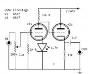
I have been breadboarding my own version of a 6sn7 preamp on the side and this one has seen enormous improvement from the regulated supply. I will post a schematic for you guys to review, but don't be too harsh as I've no real idea as to what I'm doing and this was mostly compiled from other schematics and cryptic internet discussions on multiple forums.
Schematic attached. Thinking of changing 33k on anode of first valve to 22k. Assume amplifier load 100k
Attachments
Last edited:
Hi,
@Merlin: looks ok. Are you using this as a stand alone line preamp?
Cheers, 😉
Thank you, yes.
Greetings🙂
Hi,
Here's one example of Kevin's reg:
http://www.diyaudio.com/forums/anal...ovite-6s3p-tube-phonostage-7.html#post3112139
I've seen at least one more though. Just can't seem to find it right now.
Search for Rickard Berglund on this forum and you should dig it up.
Cheers, 😉
Edit: http://www.diyaudio.com/forums/tubes-valves/90020-perfect-tube-regulator.html
Bingo. All it needs is to be set for 250VDC output.
Hi Frank,
Here is a reference to that regulator:
http://www.diyaudio.com/forums/tubes-valves/90020-perfect-tube-regulator.html#post1059442
I would change the zener voltage to 82V+5.1V (or an 87V zener) which would give you roughly 260V out - this is kind of close to the lower limit for this design. Note that I now isolate the filament of the pass tube from the cathode using something like a 100K resistor between them and a small film cap of 0.1uF rated for at least 100V greater than the output voltage of the regulator. This substantially reduces ripple injection into the output due to the interwinding capacitance present in the power transformer.
Hi,
Thx for the input, Kevin.
I've always used a separate heater xformer and let the heaters of the regulator float. So far they've all been dead quiet. Never even bothered to twist the heaters' wires either, just pushed them flat against the casing and that was that.
Cheers all, 😉
Thx for the input, Kevin.
I've always used a separate heater xformer and let the heaters of the regulator float. So far they've all been dead quiet. Never even bothered to twist the heaters' wires either, just pushed them flat against the casing and that was that.
Cheers all, 😉
Hi Frank, I've done that as well, but have possibly unjustified concerns about potential insulation failure in the cathode sleeve, particularly if the leakage resistance in the filament transformer is a bit on the low side. As long as the filament winding is not directly connected to the cathode noise injection does not seem to occur.
In the error amplifier floating the filament supply without a dc reference point and a low AC impedance to ground measurably degrades regulator ripple rejection. Injection occurs through the filament to cathode capacitance in the upper tube in the cascode error amplifier. It's quite measurable and since I use absolutely no decoupling between my regulators and their loads (the output capacitor is there for stability not effective below a few hundred Hz or higher) it is an issue I have to watch out for.
In the error amplifier floating the filament supply without a dc reference point and a low AC impedance to ground measurably degrades regulator ripple rejection. Injection occurs through the filament to cathode capacitance in the upper tube in the cascode error amplifier. It's quite measurable and since I use absolutely no decoupling between my regulators and their loads (the output capacitor is there for stability not effective below a few hundred Hz or higher) it is an issue I have to watch out for.
Hi,
@Kevin, I agree but the design approach you chose is quite different from mine as used in the phono stage in that a) the cascode of the error amp is current starved and b) the difference between Vin and V out is also unconventional as it's rather small.
On top of that the regulator is decoupled with a massive capacitor bank.
Although V out is very stable this a is mostly due to the large caps and not so much because of the regulator itself.
That said, it works fine but I admit it is a bit "odd" all in all.
Further more, I can't be absolutely certain about the heaters being floating or referenced to ground, the thing was designed in '86 after all. Either way, it's easy enough to ground the heaters.
Again, rhanks for the input. Never too old to learn, right?
Cheers, 😉
How many mA of the HT gets eaten up by the ecl85 regulator circuit? I'm about to order some new power transformers...
- Home
- Amplifiers
- Tubes / Valves
- Frank's Ultimate Tube Preamp