Hi,
The PSU was designed with four separate identical xformers sporting separate heater and HT windings.
I honnestly can't remember the VA rating I used but obviously the bulk of the current goes to the heaters.
A margin of 25 to 30 % won't do any harm.
Cheers, 😉
The PSU was designed with four separate identical xformers sporting separate heater and HT windings.
I honnestly can't remember the VA rating I used but obviously the bulk of the current goes to the heaters.
A margin of 25 to 30 % won't do any harm.
Cheers, 😉
Hi,
The PSU was designed with four separate identical xformers sporting separate heater and HT windings.
I honnestly can't remember the VA rating I used but obviously the bulk of the current goes to the heaters.
A margin of 25 to 30 % won't do any harm.
Cheers, 😉
Hi Frank, sorry to come back to you again.
The HT winding for one circuit is quoted as 300mA in the part list on page 4 of the thread, so +30% means 400mA. Do you think this is about right. Yes I know is was a long time ago, but HT windings that can deliver 400mA at 400V are difficult to find (so far I can only find a 600V and they cost 200 euro each)
Hi,
The original xformers were sourced from RS Components. 300mA should suffice.
200 Euro each sounds excessive to me but hat preamp was not exactly cheap to build either.
Back in those days valves were still reasonably priced though.
Up to you but this isn't a cheap project, it never was.
Cheers, 😉
The original xformers were sourced from RS Components. 300mA should suffice.
200 Euro each sounds excessive to me but hat preamp was not exactly cheap to build either.
Back in those days valves were still reasonably priced though.
Up to you but this isn't a cheap project, it never was.
Cheers, 😉
I'll go with the Hammond 369KX with 300mA for HT and 5A for the 6.3V heaters + another tranny for the 12V dc heaters.
Thanks again Frank.
Thanks again Frank.
Hi,
I hope I am not late on that thrad, tring to find the best PSU for my SRPP preamplifier (the anzai tiplogy)
At the moment I use a el86 driven by 1/2 ecc83 but I think ecl82 can do more and I need some advice.
I have several atempts for a decent ecl82 HT psu as follows:
I hope I am not late on that thrad, tring to find the best PSU for my SRPP preamplifier (the anzai tiplogy)
At the moment I use a el86 driven by 1/2 ecc83 but I think ecl82 can do more and I need some advice.
I have several atempts for a decent ecl82 HT psu as follows:
Attachments
Last edited:
Hi,
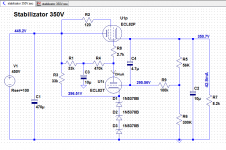
A suitable PS.
I used one for each channel.
The 4K7 trimpot allows to set the output of the regulator to output 350VDC.
The heater and biasing scheme isn't included in the drawing.
Basically I'd use 2*15VAC, each of which bridge rectified, filtered and regulated using 7812s of sufficient current rating.
Cheers,😉
Super late to the party but does anyone have any photos of this completed beast ? Thinking I want to build this thing but I am alittle confused on the best way to ground it.
Hi,
Thank you for taking an interest.
Even I do not even have a photo but the best way to build it is to use separate chassis/housings for PSU and preamp unit.
Grounding should be star ground at the quietest point of the PSU.
It should be dead quiet regardless of volume output. No humm, no hiss. Quiet.
Cheers, 😉
Thanks, I am reading Merlin's excellent book, need to wrap my head around grounding, seems like everyone has their own way of doing it.
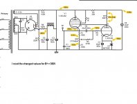
hello dear participants. Could you please tell me what changes should be made in the circuit, if we make it on 6sn7 tubes? With the nominal values indicated on the diagram I get a level drop below 100Hz and above 10kHz....
Hi,
Thank you for your interest in the circuit but I'm puzzled how you get these frequency deficiencies.
How did you measure these?
The 6SN7 is pretty close to the 12BH7A or 12AU7A for that matter. They should all work just fine with the same component values you find in the schematic.
Cheers, 😉
Thank you for your interest in the circuit but I'm puzzled how you get these frequency deficiencies.
How did you measure these?
The 6SN7 is pretty close to the 12BH7A or 12AU7A for that matter. They should all work just fine with the same component values you find in the schematic.
Cheers, 😉
Hello, Frank! Thanks for helping out! I believe my problem was due to the sound card. But I have a couple more questions. First question, is it normal that the sound is noticeably going through the off buffer? I think it goes through the 1M resistor between the input and output capacitor, if the input impedance of the next stage is quite high. Second question - my measurements show a second harmonic level of about -78dB. Is this normal for a circuit with this kind of feedback? Thanks again!
Hi,
Good to hear it's not the circuit that is at fault here. It's a White cathode follower which is a rather complicated circuit with some coupling caps in the direct signal path and it also has an insertion loss.
That means that it will reduce the gain of the input a little.
The main advantage of the circuit and hence my use of it here is very low output impedance and decent current which allows it to drive long-ish interconnects with ease.
The very low distortion levels are quite normal for this type of circuit. Although not quite apparent, the nfb is pretty high. No free lunch there.
Hope this helps,
I quite like the performance of a pentode cathode follower with a 60H/500ohm DCR choke in the cathode R position, with cathode follower feeding an autoformer volume control. Low input capacitance, 100k G1 resistor is an easy load to drive, low output impedance, taken lower as volume is reduced. I used a 12P1L in the one I built. I think it sounds quite good, very transparent, strong dynamic contrast and downward dynamic range, quiet zero noise (unmeasured, so subjective speculation ;-) ) even with AC heater power. Easy to change cathode current to taste by varying the G2 voltage. With a 2V source there aren’t too many challenges driving most power amps to maximum power. Balanced sources and outputs can be accommodated with input and output transformers.PREAMP.
Hi,
You could certainly do that, my only concern with this kind of tube is the high heater current and mayby microphony as well.
Other candidates are the noval range such as the 12B4A, 6S4, 6C19P and 12BH7A.
I had the latter in mind since it is still currently produced and a useful type of tube to have around.
Since we are going to need two triodes for the White CF, I think it is a good candidate.
In case you need a bit more power, to drive headphones the 6AS7G cicrcuit as shown on the Headwize site certainly is a good choice.
Basically, what we need is low output Z and good drive.
Ciao,😉
My 2cents, ymmv etc etc
I may not have worded my question accurately. My buffer is skipping sound without power. I don't mean for a certain amount of time after unplugging. It skips sound at any time. Is this normal?Hi,
Good to hear it's not the circuit that is at fault here. It's a White cathode follower which is a rather complicated circuit with some coupling caps in the direct signal path and it also has an insertion loss.
That means that it will reduce the gain of the input a little.
The main advantage of the circuit and hence my use of it here is very low output impedance and decent current which allows it to drive long-ish interconnects with ease.
The very low distortion levels are quite normal for this type of circuit. Although not quite apparent, the nfb is pretty high. No free lunch there.
Hope this helps,
- Home
- Amplifiers
- Tubes / Valves
- Frank's Ultimate Tube Preamp