No, I intentionally wrote that it goes on for a long time. A day or more. I know what capacitors are))
Hi,
Either the PSU capacitance is huge or the unit does not really switch off ?
Strange....
Cheers, 😉
Either the PSU capacitance is huge or the unit does not really switch off ?
Strange....
Cheers, 😉
It's not an input resistor. If the resistance of this resistor is less than needed, it will let the signal through to the output.
Hi,
Resistors do not stop AC input. Besides that, what has this got to do with your problem?
Cheers,
Resistors do not stop AC input. Besides that, what has this got to do with your problem?
Cheers,
I'm sorry, Frank, I'm probably not making myself clear again. I believe that if the power is off, the signal can go from the input through C1- R1-C3. According to the numbering in my drawing.
Hi,
Sure it will leak through to ground.
You're supposed to put the mute switch on so the output is shorted and switch off your source too.
Hope this helps?
Sure it will leak through to ground.
You're supposed to put the mute switch on so the output is shorted and switch off your source too.
Hope this helps?
If there is no “mute” switch, the signal at the output (if the power is not turned on) will weaken by a factor of about 10 (the ratio of resistors R1/R6), right? But if resistor R1 is faulty and has a lower resistance, the signal will be stronger, correct? There is no other way for the signal (if the power is off), am I right? I just want to understand where else I could be wrong and where to look for the source of the problem.

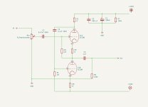
Dear Frank, I really like the sound of your preamp. My friend is also delighted with how it neatly ennobles the sound of his inexpensive DAC. So I want to try to make a second version as a buffer for his amplifier and use lower anode voltage and bi-polar power supply. I was guided by thoughts from here https://www.tubecad.com/2019/04/blog0462.htm. Could you please check if I have drawn your schematic correctly for the bi-polar variant?
Attachments
Hi,
At first glance the B+ should be roughly 200VDC.
By bi-polar you refer to using a B+ and B- rail I suppose.
Calculations should done to define the R values that are missing . I think formulas can be found on Tubecad's site.
Cheers and happy holidays.
At first glance the B+ should be roughly 200VDC.
By bi-polar you refer to using a B+ and B- rail I suppose.
Calculations should done to define the R values that are missing . I think formulas can be found on Tubecad's site.
Cheers and happy holidays.
Thank you, Frank. Yes, that's right, I want to use +100V and -100V relative to ground, ie between cathode and anode about 200V. Have I connected R4 correctly? Or is it better to connect it to ground?
Hi,
R4 is OK but the top triode will make the B+ go down depending on the Rp of it.
Is there a sample schematic for this on Tubecad's site. If so I must have missed it.
Cheers, 😉
R4 is OK but the top triode will make the B+ go down depending on the Rp of it.
Is there a sample schematic for this on Tubecad's site. If so I must have missed it.
Cheers, 😉
In that article, there's this option - https://www.tubecad.com/2019/04/15/White Cathode Follower with Bipolar Power Supply and Rk.png
Hi,
Yes, saw it now. Sorry.
Any reason why not choose the ECC99 that runs on slightly higher voltages?
Off to bed, 😉
Yes, saw it now. Sorry.
Any reason why not choose the ECC99 that runs on slightly higher voltages?
Off to bed, 😉
- Home
- Amplifiers
- Tubes / Valves
- Frank's Ultimate Tube Preamp