Hi,
That's more like it.
Guess I redesigned that reg to take a 12AX7A after all.
Cheers, 😉
Per post #74 this would appear to be the power supply
That's more like it.
Guess I redesigned that reg to take a 12AX7A after all.
Cheers, 😉
Hi,
That's either going to be a White CF or an SRPP but it's in here somewhere...
Cheers, 😉
Could someone post the schematic for the CD line preamp feeding a ECC99....
That's either going to be a White CF or an SRPP but it's in here somewhere...
Cheers, 😉
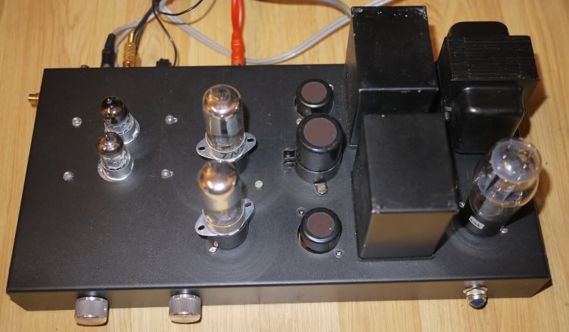
I have just built this for use with my home made stereo KT88 SE amp. see pic.
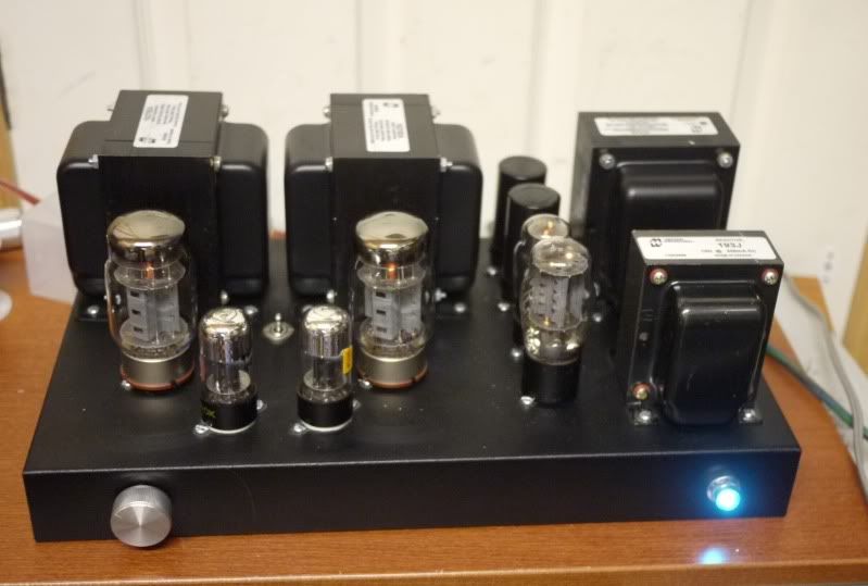
I have added this ECC88 phono stage to one input and I am amazed how good it sounds.
http://phonoclone.com/diy-pho3.html
I used AC heaters throughout and there is no hum at all. The phono stage is seperately screened which allowed me to route the heaters outside of the can.
The power transformer came from a 50's amp chassis I got off eBay and the two chokes came from an old regulated HT PSU.
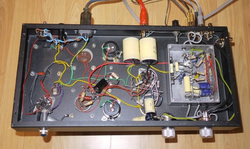
I am using 7N7 valves with home made 6SN7 Octal to 7N7 Loctal adapters.
The side Phono sockets are now tape out( just fed via 2 x10k resistors from the top of the volume control). I have used these to record LPs on my Mac with excellent results.
My thanks to Frank for a great and simple design.
I have added this ECC88 phono stage to one input and I am amazed how good it sounds.
http://phonoclone.com/diy-pho3.html
I used AC heaters throughout and there is no hum at all. The phono stage is seperately screened which allowed me to route the heaters outside of the can.
The power transformer came from a 50's amp chassis I got off eBay and the two chokes came from an old regulated HT PSU.
I am using 7N7 valves with home made 6SN7 Octal to 7N7 Loctal adapters.
The side Phono sockets are now tape out( just fed via 2 x10k resistors from the top of the volume control). I have used these to record LPs on my Mac with excellent results.
My thanks to Frank for a great and simple design.
Last edited:
hello, I build this preamp. big problem. huge hum when input is disconnect. sound like oscillate. and gain way too high. already full volume with volume pot turned just a little from 0. and hum increase with volume pot. middle loudest. I build dc coupled 6sn7 version. help!
Frank,
Sounds good to me but what if someone wants a little bit of gain say 6db.
Jam
I would say that's reasonable especially if one uses an iPod or something similar
They only put out a little more than 1v rms with 2v peak, so you need a little
Headroom, I've ran one through a tube buffer before, and the sound was weak and the sound was strained.
Hi,
Denny, there's another thread somewhere describing the circuit Donovas is referring to:
1/2 a 6SN7 (replace with a 6CG7 if you want) direct coupled into another 1/2 6SN7 offering the necessary gain.
Problem is that people not requiring the gain sometimes end up having too much of it.....
Donovas, you could try soldering a resistor in series with the input signal in front of the volume control to attenuate the input. Start with a 20K value and replace until you find a value that suits your needs.
Alternatively, use a 50K linear pot with the wiper connected to the output lug instead of the resistor to pre-attenuate the input.
Cheers, 😉
hi frank. so high gain can normally be? could possible be that i wire something wrong but pre works defectively?
i will try the volume trick. thank you.
shunt attenuator, yes? 🙂
i will try the volume trick. thank you.
shunt attenuator, yes? 🙂
Hi,
Gain is about 6dB IIRC.
Do you happen to know the output level of the device you're hooking up to it?
It's a pretty simple circuit but errors can always happen.
If you're sure you have the pot wired correctly then I don't quite understand why you can't achieve sufficient attenuation of the input.
Can you please recheck all the wiring to the valves to make sure?
Cheers, 😉
hi frank. so high gain can normally be? could possible be that i wire something wrong but pre works defectively?
Gain is about 6dB IIRC.
Do you happen to know the output level of the device you're hooking up to it?
It's a pretty simple circuit but errors can always happen.
If you're sure you have the pot wired correctly then I don't quite understand why you can't achieve sufficient attenuation of the input.
Can you please recheck all the wiring to the valves to make sure?
Cheers, 😉
hello,
output level 4.4v. homebuilt dac.
this my first ever tube project. a lot could (and did) go wrong 😀
wiring seem ok. but maybe this wrong? I go straight from sshv2 to 2nd triode b+ on both. no post filtering. so pin 2 of both tubes connect to one point where salas shunt feed...
also, my b+ 190v.
output level 4.4v. homebuilt dac.
this my first ever tube project. a lot could (and did) go wrong 😀
wiring seem ok. but maybe this wrong? I go straight from sshv2 to 2nd triode b+ on both. no post filtering. so pin 2 of both tubes connect to one point where salas shunt feed...
also, my b+ 190v.
Last edited by a moderator:
Hi,
I see two problems:
1/ The output of the DAC is way too healthy
2/ Using a B+ of 190VDC for a circuit designed for 250VDC is a sure way to ask for trouble.
I've no idea how many volts the Salas shunt reg drops but it should be able to output 250V given the correct input voltage.
Secondly, is there no way to take the output from the DAC at a lower amplification level?
Thirdly, with any regular/standard DAC output a simple volume control and a buffer is all you'll ever need.
Cheers, 😉
hi frank,
I will go 250v and report back.
I can drop dac output yes. 🙂
even from defectiveness, it still best preamp I have ever ever hear 🙂 better than $5000 upwards stuff 😀
I will go 250v and report back.
I can drop dac output yes. 🙂
even from defectiveness, it still best preamp I have ever ever hear 🙂 better than $5000 upwards stuff 😀
Hi,
Maybe you should keep it defective then? 😀
Thanks for the compliment.
Cheers, 😉
even from defectiveness, it still best preamp I have ever ever hear better than $5000 upwards stuff
Maybe you should keep it defective then? 😀
Thanks for the compliment.
Cheers, 😉
Frank,
This is a superb thread, Just finishing the complete reading of every word. Thank you for this, plus what seems to be also be a superb pre-amp project which will be my next tube project. Still shopping for XMFs & seeing what I have in hand that would work.
Regarding the newer 1N4007 designs, some have tried the newer "UF4007" with good reviews. This may be the very last component swap I will attempt on your design. Normally I'm a vacuum rectifier person. Discrete DC filaments easy to do w/ LM317 and adjust under load the correct voltage. I enjoy the fact that you have left it up somewhat to the reader/builder the interpretation of your design, and no so 100% "turn-key" as it were, which places me right where I need to be, in my design seat. But thanks for the schematics and good words to everyone who has followed you Kind Sir. I hope to have a solid start before the years end.
Greetings from Texas!
Doug
Hi Doug,
Thank you for the kind words.
If you let me know what part(s) of the preamp you're going to build I'll gladly help you further.
The original design is rather old even it was well "ahead" of what was commercially available back then.
There are a few things I would change, the rectifiers diodes are certainly one of them.
In fact I have been pondering on doing an update for quite a while but have been postponing it due to various circumstances. C'est la vie.
Cheers, 😉
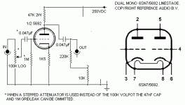
Hi,
Sorry but I don't remember the exact figures. Maybe these were mentioned in the thread?
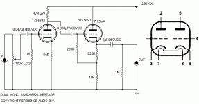
The first schematic is crippled in that you need a 1M resistor at the output and not what is shown in the drawing which is actually part of the second one.
Gain and especially output impedance of the second schematic will both be lower than the top one though.
There's also a version that direct couples the output of the first section of the valve to the second one which theoretically should sound slightly more transparent.
Cheers, 😉
Sorry but I don't remember the exact figures. Maybe these were mentioned in the thread?
The first schematic is crippled in that you need a 1M resistor at the output and not what is shown in the drawing which is actually part of the second one.
Gain and especially output impedance of the second schematic will both be lower than the top one though.
There's also a version that direct couples the output of the first section of the valve to the second one which theoretically should sound slightly more transparent.
Cheers, 😉
- Home
- Amplifiers
- Tubes / Valves
- Frank's Ultimate Tube Preamp