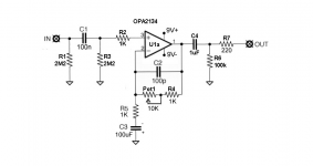
I wanted to build a circuit to buffer my guitar pickups (~19k output impedance) and as needed amplify them by ~5-20 dB for direct to DAW line in recording (10K input impedance).
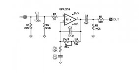
I started with a prefab circuit design, and with the help of primarily bentsnake, we modified it until we got the attached OPA2134 circuit.
I'm about ready to start building the stripboard for my first trial at the circuit. Last time I rushed into building a circuit I made an oversight and it was a mess, so I thought I would just open it up one last time in a fresh thread before I start this time for comments/criticisms.
The primary question is regarding the input stage. The original circuit I was editing had the 1K resistor there as well as both 2M2 resistors (but it was a single supply circuit and one of these resistors was related to that).
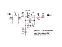
I've attached for comparison the most popular single supply buffer schematic out there for guitar - the Klon Buffer (TL072).
I'm wondering if there's anything I should simplify about my input stage (OPA2134 schematic) - remove one 2M2, change either 2M2 to 1M, remove the 1K resistor (or reduce its value), etc?
Also curious if C2 is a good value in the feedback loop.
Thanks for any final proofreading and/or comments before I start the build.
I started with a prefab circuit design, and with the help of primarily bentsnake, we modified it until we got the attached OPA2134 circuit.
I'm about ready to start building the stripboard for my first trial at the circuit. Last time I rushed into building a circuit I made an oversight and it was a mess, so I thought I would just open it up one last time in a fresh thread before I start this time for comments/criticisms.
The primary question is regarding the input stage. The original circuit I was editing had the 1K resistor there as well as both 2M2 resistors (but it was a single supply circuit and one of these resistors was related to that).
I've attached for comparison the most popular single supply buffer schematic out there for guitar - the Klon Buffer (TL072).
I'm wondering if there's anything I should simplify about my input stage (OPA2134 schematic) - remove one 2M2, change either 2M2 to 1M, remove the 1K resistor (or reduce its value), etc?
Also curious if C2 is a good value in the feedback loop.
Thanks for any final proofreading and/or comments before I start the build.
Attachments
Last edited:
your opamp is AC coupled all round, so output offset is blocked.
But check pin1 to ensure it is near zero volts, otherwise you waste/lose peak level.
To minimise offset, R3+R2 ~= R4+Pot1
Your resistor values are way too high and this will increase noise without any benefit.
reduce R5, R4 pot to 1/10th
reduce R3 to match that equation.
Then adjust C1 to get the passband you need.
Can the guitar drive a normal impedance stage?
or does it need a very impedance load?
Use one battery as per the TL72 and reduce the input impedance to a maximum of 1Meg. The volume pots are 220K so no need for 2M2!
It looks basically fine to me. The FET opamp removes DC offset worries due to imbalanced impedances seen on the opamp inputs. None of the resistor values will materially effect the offset. R1 and R3 get shunted by the source impedance of the pickup and so they contribute no noise penalty. Only comments would be that C3 could usefully be a little larger, perhaps a 6.8 or 10uf, and C2 at 100pf is eating into the top end of the audio band when the pot is getting toward 100k. Realistically you need only a 10pf or less here to tame any possibility of instability given even a half decent layout and build. Depending on what you connect this to then the output coupling cap could perhaps do with being a little larger. 560 ohm output resistor is fine but a bit excessive. You only 47 ohms or so to remove any possibility of instability with a capacitive load. Don't forget decoupling the IC. A single 10uf standard electrolytic soldered across the supply pins is all you need.
Thanks for the feedback guys.
If it will still be stable with smaller feedback resistor values, I would rather use 10K pots (than 100K) in the feedback loop, because I'm buying relatively expensive stepped attenuators. 10K pots are more versatile for future use in case this doesn't work out. eg. I could switch the circuit to fixed gain and use them as simple volume knobs on the output.
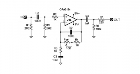
I reduced the feedback resistors to 10K pot +1K. I reduced the R5 resistor to ground accordingly to 1K. I increased the associated C3 cap to 10 uF to maintain high pass filter at ~16 hz. Lastly I reduced the output resistor to 220 ohms. I think the 100 pF C2 is now no longer a problem, as I think that forms a high pass filter at 144 kHz with 11K at the feedback resistor.
A few questions:
1) Should this still be stable with R4/R5 at only 1K?
2) I'm figuring I'll use a MLCC for C3 now that it's 10 uF - okay choice?
3) Can someone explain to me how the input stage of this circuit works? I'm happy with it as long as it does work. But I just don't get it. I understand C1 blocks DC. What does R2 do? And why do I need TWO resistors going to ground here (R1 & R3)?
Thanks again guys.
If it will still be stable with smaller feedback resistor values, I would rather use 10K pots (than 100K) in the feedback loop, because I'm buying relatively expensive stepped attenuators. 10K pots are more versatile for future use in case this doesn't work out. eg. I could switch the circuit to fixed gain and use them as simple volume knobs on the output.
I reduced the feedback resistors to 10K pot +1K. I reduced the R5 resistor to ground accordingly to 1K. I increased the associated C3 cap to 10 uF to maintain high pass filter at ~16 hz. Lastly I reduced the output resistor to 220 ohms. I think the 100 pF C2 is now no longer a problem, as I think that forms a high pass filter at 144 kHz with 11K at the feedback resistor.
A few questions:
1) Should this still be stable with R4/R5 at only 1K?
2) I'm figuring I'll use a MLCC for C3 now that it's 10 uF - okay choice?
3) Can someone explain to me how the input stage of this circuit works? I'm happy with it as long as it does work. But I just don't get it. I understand C1 blocks DC. What does R2 do? And why do I need TWO resistors going to ground here (R1 & R3)?
Thanks again guys.
Attachments
Last edited:
1) Should this still be stable with R4/R5 at only 1K?
2) I'm figuring I'll use a MLCC for C3 now that it's 10 uF - okay choice?
3) What does R2 do? And why do I need TWO resistors going to ground here (R1 & R3)?
The R1 isn't theoretically necessary, but it will prevent noises when connecting.
The R3 provides a DC path to ground for the input of the op amp, and for the capacitor as well.
The values of R4 and R5 are ok (as long as the op amp can drive 1k adequately), since the op amp is unity gain stable.
The R2 is insurance against parasitics for stability. With this value of C3, you will have a bass rolloff corner at 16Hz.
This may be a little marginal.
Last edited:
The R1 isn't theoretically necessary, but it will prevent noises when connecting.
The R3 provides a DC path to ground for the input of the op amp, and for the capacitor as well.
The values of R4 and R5 are ok (as long as the op amp can drive 1k adequately), since the op amp is unity gain stable.
The R2 is insurance against parasitics for stability. With this value of C3, you will have a bass rolloff corner at 16Hz.
This may be a little marginal.
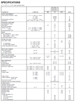
Thanks for the succinct explanation Rayma. How do I figure out if the opamp can drive 1K adequately? The datasheet is here. I've attached a screencap. If it's going to be more stable with a 20K/50K/100K pot instead (with 2K/5k/10K for R4&R5), I can order any of those instead. Whatever works.
Also, are you suggesting I increase the bass rolloff to ~20 hz? I could do so using a 4.7 uF capacitor at C3 and 1.7K resistors at R4/R5.
Attachments
Last edited:
How do I figure out if the opamp can drive 1K adequately?
If it's going to be more stable with a 20K/50K/100K pot instead (with 2K/5k/10K for R4&R5),
I can order any of those instead. Also, are you suggesting I increase the bass rolloff to ~20 hz?
I could do so using a 4.7 uF capacitor at C3 and 1.7K resistors at R4/R5.
The data sheet lists 35mA max for the output current, so 9V/.035 = 257 Ohms min, and a 1k load is fine.
I don't think stability will be an issue for this circuit, if properly constructed. Don't forget the local bypass caps.
Personally, I prefer to set rolloffs well under the audio band, around 1-2 Hz. Remember that a pole at 16Hz
means 5 degrees of phase shift at 160Hz. Also, capacitors can distort if signal voltage appears across them,
as will happen when the pole is set too high in this circuit. I would use more like 100uF here.
Last edited:
Well, we've been through all this in the previous thread, it's not really necessary to agonize over the high resistances because of noise, the environment is typically megohm inputs and outputs with guitar pickups and amps, I suggested you keep the values relatively high to avoid the rolloff creeping up as rayma suggests and restrain the size of the caps.
If you keep these values up your worries about the opamp driving capacity can be ignored, use a TL071. It's unity gain stable, your gain is 2~12, C2 is superfluous.
If you keep these values up your worries about the opamp driving capacity can be ignored, use a TL071. It's unity gain stable, your gain is 2~12, C2 is superfluous.
The data sheet lists 35mA max for the output current, so 9V/.035 = 257 Ohms min, and a 1k load is fine.
I don't think stability will be an issue for this circuit, if properly constructed. Don't forget the local bypass caps.
Personally, I prefer to set rolloffs well under the audio band, around 1-2 Hz. Remember that a pole at 16Hz
means 5 degrees of phase shift at 160Hz. Also, capacitors can distort if signal voltage appears across them,
as will happen when the pole is set too high in this circuit.
Thanks again, Rayma. I didn't realize I was supposed to want a rolloff that low. I changed that cap to 100 uF and now it should roll off at 1.59 hz. Did I orient it correctly? ie. Anode to ground, cathode towards the - input of the opamp?
For bypass caps, I intend to put a 100 nF cap from each of V+ and V- to ground right next to the opamp pin. I will also be putting a 10 uF cap from each of V+ and V- to ground.
Re: C2, if it is superfluous that is fine to me, as long as it isn't impairing the function of the board in any way. If it adds any even theoretical stabilizing effect, I'd rather just keep it, since it's only one tiny component.
I hope all the other filters and values look good. Please let me know if you see anything else that can be improved. I'm starting a diagram of my veroboard layout. 🙂
Attachments
Last edited:
If you keep these values up your worries about the opamp driving capacity can be ignored, use a TL071.
It's unity gain stable, your gain is 2~12, C2 is superfluous.
Yes, I would expect that C2 is not necessary with either op amp. I've designed a commercial circuit
that is somewhat similar and it was just fine with no capacitive compensation. This assumes a proper
pcb layout.
Last edited:
What is the purpose of the pot in the feedback loop?
I've always used only a resistor there.
Variable gain. With the pot all the way down it's unity (0 dB gain), with the pot all the way up to 10K it's a 21.5 dB gain amplifier.
At least that's the idea - we'll see how it works soon enough ...
A few questions:
1) Should this still be stable with R4/R5 at only 1K?
2) I'm figuring I'll use a MLCC for C3 now that it's 10 uF - okay choice?
3) Can someone explain to me how the input stage of this circuit works? I'm happy with it as long as it does work. But I just don't get it. I understand C1 blocks DC. What does R2 do? And why do I need TWO resistors going to ground here (R1 & R3)?
Thanks again guys.
2) Avoid ceramic capacitors in signal path as they distort much more than film types.
Variable gain. With the pot all the way down it's unity (0 dB gain), with the pot all the way up to 10K it's a 21.5 dB gain amplifier.
At least that's the idea - we'll see how it works soon enough ...
With pot turned to minimum the gain is 6dB. Only if R4 is zero (short) minimum gain will be 0dB.
With pot turned to minimum the gain is 6dB.
That's what I was thinking since the gain is going to vary anywhere from 2 to 12 depending on the pot's setting.
.
When I first saw this post I decided to sit quietly, read, and learn. I changed my mind. My two cents--maybe just one--and suggested circuit changes herewith offered.
<< 3) Can someone explain to me how the input stage of this circuit works? I'm happy with it as long as it does work. But I just don't get it. I understand C1 blocks DC. What does R2 do? And why do I need TWO resistors going to ground here (R1 & R3)? >>
R1 has nothing to do with the shown circuit, it's a load resistor for the preceding stage, which is a guitar pickup. Some pickups might not work if this resistor is omitted, and it doesn't change the shown circuit's operation in any way.
C1 does not just block DC, it's also part of a filter. Please see the circuit notes in the link below.
R3, along with setting the input impedance (working with R1), is the bias current resistor for U1. Without this resistor the circuit will not operate.
<< How do I figure out if the opamp can drive 1K adequately? >>
You don't do any figuring, you look in the data sheet, which will say something like "drives a 600 ohm load." BUT this is deceptive because what might constitute a "load" is an engineering question. It's best by far to follow the rule of thumb quoted below.
<< If it's going to be more stable with a 20K/50K/100K pot instead (with 2K/5k/10K for R4&R5)... >>
It just doesn't work that way. The feedback network doesn't directly affect stability/not. Never make R5 less than 2.2k, follow the rule of thumb quoted below.
<< ...increase the bass rolloff to ~20 hz? >>
Is there a valid engineering reason for doing this? Rhetorical question, of course. As a rule of thumb (different rule of thumb), lower is better.
<< For bypass caps, I intend to put a 100 nF cap from each of V+ and V- to ground right next to the opamp pin. I will also be putting a 10 uF cap from each of V+ and V- to ground. >>
Is this what the data sheet calls for? If not, do you have a reason for changing the data sheet spec? More rhetorical questions, you see.
<< I would rather use 10K pots (than 100K) in the feedback loop, because I'm buying relatively expensive stepped attenuators. >>
I advise against this unless you're certain of the construction of such attenuators. Consider what happens if the wiper of Pot1 loses contact.
<< I reduced the feedback resistors to 10K pot +1K. I reduced the R5 resistor to ground accordingly to 1K. I increased the associated C3 cap to 10 uF to maintain high pass filter at ~16 hz. Lastly I reduced the output resistor to 220 ohms. I think the 100 pF C2 is now no longer a problem, as I think that forms a high pass filter at 144 kHz with 11K at the feedback resistor. >>
R5 doesn't go to ground, it goes to C3. After that, are there valid engineering reasons for making these changes? Rhetorical again. Please see the following circuit notes.
CIRCUIT NOTES:
See post #60 here: http://www.diyaudio.com/forums/anal...ost-non-inverting-opamp-buffer-circuit-6.html
Additionally:
The Zin of this circuit is about 1 meg (R1 || R3). This is about ideal for a guitar pickup and should not be reduced.
R2 and R7 are changed to more reasonable values that are commonly used for these resistors.
C2: see post #4 in this thread.
R4 and R5: These are changed to comply with the rule of thumb: unless you know what you're doing and have good reason, do not put less than a 2k resistor on an op amp output. <~ this is the rule of thumb referenced above
C4 is a do-all value that will successfully feed any following cicuit without loss of bass notes.
R6 is omitted because its only function is to create a low pass filter together with C4. But the following stage will have its own low pass filter, and filters should never be connected in series without good reason.
.
Attachments
Last edited:
Agh !!!!!......
If it will still be stable with smaller feedback resistor values, I would rather use 10K pots (than 100K) in the feedback loop, because I'm buying relatively expensive stepped attenuators. 10K pots are more versatile for future use in case this doesn't work out.........................
an open circuit in the feedback loop will momentarily take the opamp gain to it's maximum open loop gain, maybe 100000 times (+100dB)
That will output rail voltage virtual squarewaves to the next stage.
You must use a make before break, if you use a switcher.
Agh !!!!!
an open circuit in the feedback loop will momentarily take the opamp gain to it's maximum open loop gain, maybe 100000 times (+100dB)
That will output rail voltage virtual squarewaves to the next stage.
You must use a make before break, if you use a switcher.
That's a very important point actually if you are going from a pot to a switched attenuator.
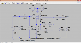
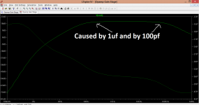
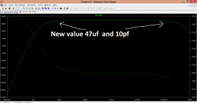
This shows the circuit of post #10 (with added 2k load) You can clearly see the effect of the 1uf output coupling cap with the LF response falling away and also the 100pf cap on the hf response. The third image is with these replaced by 47uf and 10pf which would be acceptable compromises. The pot was at 10k.
The .asc file is attached. (Click my signature line to see how to use it)
The .asc file is attached. (Click my signature line to see how to use it)
Attachments
- Status
- Not open for further replies.
- Home
- Source & Line
- Analog Line Level
- Critique this noninverting opamp buffer/amplifier please? Almost time to build...