I think the closest match I can go with is 5K on R5 then. If I understand your post, then in this case the bridge humbuckers will create more noise than the buffer/amplifier circuit, and the buffer/amplifier circuit will create (slightly) more noise than the neck humbuckers.
OK, that puts the noise in the same ballpark. This is just the feedback network contribution. You can go lower, but at the cost of a bigger cap, and maybe a different opamp. We haven't considered the opamp noise.
Here's a page with a link to a spreadsheet noise calculator:-
Op Amp Noise?but what about the feedback? | EDN
With the OPA134 I get Rs =39%, Rg (R5) = 31%, OPA Vnoise = 29% noise contributions respectively; 4.3dB total. Quite a lot better than TL072 @ ~8dB, but it's got quite a lot more bandwidth, so possibly less tolerant of quirky installation.
Thanks. From that link:
An externally hosted image should be here but it was not working when we last tested it.
They're suggesting for my circuit R4||R5 should be << the source (pickup) impedance.
With the pot at 50K, R4||R5 = 4545 ohms. Slightly less than half of each pickup's total impedance, but not <<.
With the pot at 0K, R4||R5 = I guess 0 ohms?
So acceptable. But on the other hand I could always go back down to 20K for R2 and 2.2K for R5. At that level, my opamp loading is 2.2K+20k ||10560 = 7156 (at maximum gain) or 2.2K || 10560 = 1820 (at minimum gain). So my opamp loading becomes slightly less optimal at minimum gain though still good.
Seems it probably doesn't matter either way. Maybe slightly more distortion with the 20K pot (due to potentially suboptimal loading). Maybe slightly more noise with the 50K (though probably not since I really am only trying to get 100 dB signal to noise after maybe ~10dB boost and maybe I'm wrong but I don't think that's very much to ask for with this circuit).
Seems either way, I'm pretty close to done on this, since we've hammered out most of the other kinks. I'm inclined to just stick with 50K, since R4||R5 is going to be universally less than my pickup impedances on that one, so if I'm understanding correctly, they shouldn't be any significant noise contribution over what the pickup resistances are creating themselves.
Only remaining questions I think I have are:
- Might the ~6" length of the leads attaching Rpot to the board screw anything up, as per chip_mk's comment? This would be a waste of time putting all this together only to have that ruin it somehow, eg. through cable capacitance or some other factor I'm not aware of...
- Is there any theoretical value to having R2 > 100? eg. at 220 or 560? Or is 100 the maximum useful value that it could conceivably be?
Lastly, I'm just going to say thank you to everyone again for participating in this thread and discussion. It's been truly invaluable. I'll be away from my computer for the rest of the week (starting tomorrow evening), so it's been good to have the focused time this weekend to get this mostly hammered out. I feel mentally tired but better overall having gotten through it. 🙂
Last edited:
A zillion posts in the last 12 hours. Are we sorted ?
6" of wire to the pot. If its all in a metal box then there should be no real problem although I would keep the small 10pf cap in this case. It does no harm and virtually guarantees stability.
6" of wire to the pot. If its all in a metal box then there should be no real problem although I would keep the small 10pf cap in this case. It does no harm and virtually guarantees stability.
Did I do that right? Also does R5 not figure in somewhere to this load calculation?
Did you get an answer to this ?
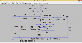
To calculate the load and peak currents we assume that caps C3 and C4 have zero reactance. In other words we assume they are shorted out. That's realistic because we have chosen them to have no effect within the audio pass band.
So we look at the load on the output which is 10k + 100 ohm (10.1k total) and the load presented by the feedback network. The opamp draw essentially no current from the feedback components (its a very high impedance node) and so the load of the feedback network with the pot at zero ohms is 220 ohm + 2k2 (2.42k total).
Those two loads (the 2.42k and 10.1k are effectively in parallel) and so the total load is 1952 ohms.
What would the peak opamp output current be. Worst case and assuming the opamp could reach to +9 and -9 volts we get -/+ 4.6milliamps.
The simulation should agree. Lets prove it. I have added a 0.1 ohm resistor to allow measurement of current. The input voltage has been set such that the output is exactly 3 volts RMS (you could use any figures as long as the opamp isn't overdriven).
The current is 1.5369 milliamps RMS.
The load impedance Z is 3/1.5369e-3 which is 1952 ohms. So the simulation and theory agree.
The sim left the caps in place because we know the values chosen have no effect within the audio passband.
Attachments
That removed resistor does nothing when the interconnect cable is connected at both ends....................... I just re-read your posts and took out that 100K (then 2M2) resistor to ground at the output which was as you said just there for a filter which was redundant................
It's when the interconnect cable is removed, even at one end only, that the resistor does anything.
The DC blocking cap isolates any DC in the circuit from the output terminal.
Except that capacitors leak, some leak very badly and others so little it is virtually unmeasurable.
Using a resistor after that DC blocking capacitor diverts most of the leakage current to Audio Ground.
eg.
A DC blocking cap that leaks 1uA when the DC across it is 10V.
Using a 100k resistor will divert most of that leakage to ground and leave the output terminal @ ~ 100mVdc, much better than having 10Vdc at the output terminal.
I generally use 2M2 at input and output DC blocking capacitors.
That probably limits my leakage to less than 10nA, for tolerable DC on the HOT pin of the terminal sockets. This will still "click" if I "hot plug".
Last edited:
My simplified formula was wrong..............The problem I'm encountering is based on AndrewT's calculation formula for establishing the total output load on the opamp (see post #38). If R4 is 0 or near zero and the pot is turned to 0 as well, the output load of the opamp drops dramatically compared to the "ideal" of around ~2K+ and distortion rises.
Unless there is something incorrect about this calculation/reasoning in post #38. I suspect there must be but I'm not sure what. ie. If you set the feedback resistor as 1 ohms and turn the pot to 0 ohms, according to AndrewT's formula, the total load on the opamp becomes 1||10100 = 1 ohm, which would be well below the acceptable opamp limits. I don't get it.
So you would suggest putting that 2M2 R6 resistor at output back in to ground? If there is no harm and it will theoretically prevent pops, will do.
I excluded the lower leg of the NFB. The lower leg must be included for accuracy.
It's a calculation I do for the NFB of power amps. I MUST ensure that the dissipation in the two NFB resistors is much less than 10% of the resistor Pmax rating. In all of these the lower leg resistor is much lower than the upper. There was my oversimplification that led to the significant error.
Mooly has explained it well a few posts back.
- Might the ~6" length of the leads attaching Rpot to the board screw anything up, as per chip_mk's comment?
Capacitor connected between inverting input and ground can cause instability. That’s why it’s advised to minimize the stray capacitance from this node by shortening the leads. It's difficult to tell without trying at which amount the stray capacitance starts causing stability issue.
If pot has to be remote from opamp, I think it’s possible to prevent excessive stray capacitance by using shielded cable, core connected to inverting input and shield connected to R4. But this is not end of the problems. If you unplug the pot from circuit (I suppose it will be pluggable) while power is on, it will break NFB loop which will immediately turn the output to either positive or negative rail (+9V or -9V) and huge thump will occur.
Perhaps keeping pot in NFB is not optimal in this case. Alternative is to set sufficient fixed gain of the opamp with fixed resistor values and make volume control by a 5k pot at the output. (5k is not difficult load for opamp and the output impedance will be reasonably low, i.e. 1k25 in worst case).
What is the expected signal level (voltage) from the pick-up?
Pot will not be pluggable. It will be soldered directly into the stripboard by ~3" in each direction of 22 gauge likely solid (though possibly stranded) core wire.Capacitor connected between inverting input and ground can cause instability. That’s why it’s advised to minimize the stray capacitance from this node by shortening the leads. It's difficult to tell without trying at which amount the stray capacitance starts causing stability issue.
If pot has to be remote from opamp, I think it’s possible to prevent excessive stray capacitance by using shielded cable, core connected to inverting input and shield connected to R4. But this is not end of the problems. If you unplug the pot from circuit (I suppose it will be pluggable) while power is on, it will break NFB loop which will immediately turn the output to either positive or negative rail (+9V or -9V) and huge thump will occur.
The entire body cavity will be shielded with copper tape and this copper tape will be grounded on output via the 13 pin guitar cable.
No way to approximate the effect of stray capacitance? Too bad since I don't have a good way to "test" the performance of the circuit once in place. It's really just a "does it sound okay?" test at that stage, and my ears aren't perfect.
I just took 6 feet of 22 gauge solid core wire and jammed the ends into my capacitance holes on my multimeter. Read 2, then 1, then after a few seconds 0 pF. It seems tiny if there is any capacitance at all. It looks like I would need a 100 ft+ roll or a much more sensitive multimeter to quantify exactly how much.
Perhaps keeping pot in NFB is not optimal in this case. Alternative is to set sufficient fixed gain of the opamp with fixed resistor values and make volume control by a 5k pot at the output. (5k is not difficult load for opamp and the output impedance will be reasonably low, i.e. 1k25 in worst case).
That was the original alternative plan. Only I'd be using a 10K output pot (impedance max 2.5k), since that's the lowest available in stereo stepped continuous action attenuators like I'm planning on using. A 2.5K output impedance into a 10K input is not exactly perfect from what I understand but shouldn't be too bad?
So that's still Plan B. I'd rather have the pot control the boost though as per Plan A.
What is the expected signal level (voltage) from the pick-up?
I'm not sure? They don't generally specify that. According to Wikipedia: "The output voltage of magnetic pickups varies between 100 mV rms to over 1 V rms for some of the higher output types. A hard strum on all 6 guitar strings can produce a larger output voltage swing, typically peak voltages of +/- 5 volts for single coil pickups and +/- 10 volt peaks on dual coil pickups"
Last edited:
There's something wrong with your measuring technique.............I just took 6 feet of 22 gauge solid core wire and jammed the ends into my capacitance holes on my multimeter. Read 2, then 1, then after a few seconds 0 pF. .............
6' of twisted 2core should have a lot more capacitance (core to core) than 0pF !
depending on cable, maybe somewhere from 60pF to 200pF for 6' (1.8m)
overloading should be avoided......................
I'm not sure? They don't generally specify that. According to Wikipedia: "The output voltage of magnetic pickups varies between 100 mV rms to over 1 V rms for some of the higher output types. A hard strum on all 6 guitar strings can produce a larger output voltage swing, typically peak voltages of +/- 5 volts for single coil pickups and +/- 10 volt peaks on dual coil pickups"
That would require a very high supply voltage. Phantom supplies are typically 48Vdc.
There's something wrong with your measuring technique.
6' of twisted 2core should have a lot more capacitance (core to core) than 0pF !
depending on cable, maybe somewhere from 60pF to 200pF for 6' (1.8m)
It's not twisted 2 core. It's just a single strand of solid core 22 gauge hookup wire, which is how it will be used to make the connections from board to pot in the design. I don't think I need to twist anything since the guitar cavity is shielded.
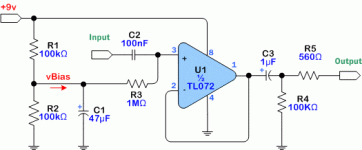
I don't know if those numbers are realistic or not. It's uncited wikipedia. Likely gibberish. Like I've said before, the most common guitar buffer is the attached, powered by a 9V battery and it works fine.overloading should be avoided.
That would require a very high supply voltage. Phantom supplies are typically 48Vdc.
Attachments
Last edited:
Pot will not be pluggable. It will be soldered directly into the stripboard by ~3" in each direction of 22 gauge likely solid (though possibly stranded) core wire.
I just noticed, the length you mention is in inches not foot. So 3 inches should not be a problem but 6 foot (as I previously misunderstood and mixed ' and ", sorry I mostly use metric units) could be excessive. Still it won’t harm to connect pot by short shielded cable as previously explained, although not critical.
you NEED 2 cores.It's not twisted 2 core. It's just a single strand of solid core 22 gauge hookup wire, which is how it will be used to make the connections from board to pot in the design. I don't think I need to twist anything since the guitar cavity is shielded...............
The signal circuit is a CIRCUIT.
All the electricity that comes OUT must come back.
The electricity does this by passing along one wire of the pair and returning along the other wire of the pair. These two wires you will see me describing as the Flow and Return pair.
For low interference pickup, that pair must be close coupled and preferably a twisted pair. referred to as UTP, unscreened twisted pair.
For more interference protection the twisted pair can be inside a screening shield. This would be called screened twisted pair.
Better again is screened star quad. This is commonly used as microphone cable.
Now go and pick up 6' of close coupled bell wire or similar and measure the core to core capacitance. Compare to the wide spaced cores of a two core mains cable.
Compare to a small diameter coaxial and to a large diameter coaxial.
Last edited:
I don't know if those numbers are realistic or not. It's uncited wikipedia. Likely gibberish. Like I've said before, the most common guitar buffer is the attached, powered by a 9V battery and it works fine.
The strength of plan A (pot in NFB loop) is it is possible to prevent overload by turning the pot to right value. Plan B avoids some potential issues as discussed but needs care when choosing gain that is the best compromise between avoiding overload and noise.
cords are small core wires.
cables are larger core wires.
See cables and cords.
The number of separately insulated cores is not relevant to whether it is a cable or a wire.
unfortunately the words get all mixed up in common usage.
cables are larger core wires.
See cables and cords.
The number of separately insulated cores is not relevant to whether it is a cable or a wire.
unfortunately the words get all mixed up in common usage.
.
Capacitance between conductors is not usually a real-world issue unless you're working in the frequency band of, say, radar.
What is an issue is that unshielded conductors are all-band antennas. This is probably not a big problem in a home environment (although it might be), but these days any sort of performing environment is likely to be a mishmash of radio frequencies that can enter audio equipment as noise.
Of course, a metal enclosure provides RF (radio frequency) shielding, which usually stops the problem before it starts.
Otherwise, the first line of defense is simply to twist conductors together, including the three conductors going to a remote pot. This results in some noise cancelling (literally one noise cancels another) and will likely solve or prevent living room interference--or might do the job entirely.
But by far the best solution is shielded cable. Consumer setups would use a one- or two-conductor shielded cable. A two-conductor cable is called, assuming #18 wire, "18-2 shielded cable w/drain." I'll explain the "drain" part in a sec.
Pro setups might use an additional conductor, so the shield functions only as that. "18-3 shielded cable w/drain."
That drain:
Top grade shielded cable has a woven copper shield. No drain needed.
But other cable might be shielded with a wrap of metalized plastic (aluminized Mylar). This is fine, but it's impossible to solder the plastic, and difficult to clamp it, so connecting the shield to ground is iffy. Enter the drain.
The drain is simply a single bare conductor, probably of a smaller gauge than the actual insulated conductors, that runs the length of the cable. This is the connection to the plastic shield, and therefore the conductor to be grounded.
CAUTION: Not all plastic-shielded cable has a drain. If the specs don't specifically state that there's a drain, then probably there is none.
Shopping note: by far the cheapest way to buy shielded cable is to buy a premade patch cord--three feet, twenty feet, whatever--and cut it up as needed. It's a "patch" cord or cable because it has male connectors on each end.
However, some vendors describe their patch cords exactly, some don't, so this can take a lot of shopping. Asian vendors on eBay might be a good bet.
For some purposes it might be worthwhile to consider Ethernet cable, although its use is limited to pairs, and it's not exactly robust. BUT it must be a shielded cable used with grounded connectors, so it's of limited utility.
By the way, it's a "cable" because there are two or more conductors. Any single conductor is just a piece of wire.
.
Last edited:
you NEED 2 cores.
The signal circuit is a CIRCUIT.
All the electricity that comes OUT must come back.
The electricity does this by passing along one wire of the pair and returning along the other wire of the pair. These two wires you will see me describing as the Flow and Return pair.
For low interference pickup, that pair must be close coupled and preferably a twisted pair. referred to as UTP, unscreened twisted pair.
For more interference protection the twisted pair can be inside a screening shield. This would be called screened twisted pair.
Better again is screened star quad. This is commonly used as microphone cable.
Now go and pick up 6' of close coupled bell wire or similar and measure the core to core capacitance. Compare to the wide spaced cores of a two core mains cable.
Compare to a small diameter coaxial and to a large diameter coaxial.
I'm talking about ~3" of wire (in each direction) sitting inside a small copper shielded-to-ground guitar cavity. I could be wrong, but I don't think it honestly matters whether they're twisted together or not. If it helps, I can twist them. No big deal.
But I certainly don't think I need additional shielding on the pair if the cavity is lined with copper tape which is grounded. I can't imagine where interference could be coming from in that case. My understanding is added shielding like screened star quad just has higher capacitance. Star quad mic cables tend to be the highest capacitance you can get.
I think there is nothing lower capacitance than a plain, straight wire, which is what I'm using. I think it is fair to expect 6" of straight 22 gauge hookup wire to be essentially 0 pF and thus noncontributable to the circuit? It's important though because even the tiniest bit of capacitance around the feedback pot in that feedback loop seems to throw off the frequency response dramatically.
.
Capacitance between conductors is not usually a real-world issue unless you're working in the frequency band of, say, radar.
What is an issue is that unshielded conductors are all-band antennas. This is probably not a big problem in a home environment (although it might be), but these days any sort of performing environment is likely to be a mishmash of radio frequencies that can enter audio equipment as noise.
Of course, a metal enclosure provides RF (radio frequency) shielding, which usually stops the problem before it starts.
And that's what most of us do with guitar cavities - we line them with copper tape, make sure it's all conducting perfectly to ground, and then just use single core straight wire hookups - no twisting, no shielded wires (unless they need to leave the copper lined cavity for some reason).
I think this is considered reasonable.
'm talking about ~3" of wire (in each direction) sitting inside a small copper shielded-to-ground guitar cavity. I could be wrong, but I don't think it honestly matters whether they're twisted together or not.
The rule is, as always, simple. If the wires are long enough to twist, then do. If not, then don't. Of course don't make wires longer just so they can be twisted.
While I have metaphorical pen in hand, I wasn't going to say anything, but I've wondered, so I'm going to wonder out loud.
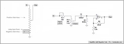
What purpose is served by having an additional gain control? I ask because there's already a gain control--both negative and positive gain--in the form of the volume knob. A "less than unity" area is present in all volume controls all the time. Usually it's of no interest, but it's there.
This might (or might not) be hard to picture at first, so I've tried to illustate it on the left side of the image below. Along with that:
Consider that the least possible output of a circuit (or component) is zero. There can be what we call negative gain, but there's no such thing as a negative output. What we call negative gain is actually an output of less than unity compared to the signal source.
Consider, for instance, a 1 volt signal source feeding a pot (a volume control). Consider that the pot's output is to a buffer, which has unity gain.
At its maximum setting the pot wiper picks up 1 volt and sends it on to the buffer. The buffer output is 1 volt, unity gain.
But at a 50% setting the pot wiper picks up 1/2 volt and sends it on to the buffer. The buffer output is 1/2 volt, which is unity gain for the buffer, but negative gain compared to the signal source.
Now consider an op amp set for a gain of, for instance, 5. Same pot, same 1 volt signal source.
At its 20% setting the pot wiper picks up 1/5th volt, which is sent on to the op amp and amplified 5 times. The op amp outputs 1 volt, unity gain compared to the signal source.
But at any setting below its 20% point the pot wiper picks up less than 1/5th volt, so the output of the up amp is less than 1 volt, negative gain compered to the signal source.
Of course, the "less than unity" area might be too small to be sufficient for a given purpose. Enter the level control shown on the right side of the posted image.
The component values are arbitrary, but in the shown circuit it can be seen that the Rv1 level control at its maximum resistance setting (CCW) effectively halves the effect of volume control Rv2. So in the given example, with a gain of 5, what I'm calling the less than unity area now extends to 40% of Rv1's rotation. Of course these values can be as wished.
So I wondered about the contortions. So wondering out loud.
.
Attachments
Last edited:
CORRECTION:
"...So in the given example, with a gain of 5, what I'm calling the less than unity area now extends to 40% of Rv2's rotation..." is of course what I meant to say. Rv2, not Rv1.
.
"...So in the given example, with a gain of 5, what I'm calling the less than unity area now extends to 40% of Rv2's rotation..." is of course what I meant to say. Rv2, not Rv1.
.
I would try to explain rationale of using shielded cable for minimizing stray capacitance. Although not particularly relevant in this case since the length is relatively short (3"), simply I would like to share this technic.
There is always certain amount of parasitic capacitance from conductors connected to inverting node of the opmamp to surfaces connected to ground (housing, ground planes, power plains, etc...). Depending on circuit, certain value of this parasitic capacitance can affect stability.
If a component in NFB loop is placed on considerable distance, the lead from inverting node going to that component could add much parasitic capacitance. However if the lead is actually core of a shielded cable (e.g. flexible audio interconnect cable), the shield can electrostatically isolate it from surround if properly connected.
If shield is connected to GND the cable capacitance will actually add a lot of unwanted capacitance to GND. Not a proper way.
But if shield is connected to the output (or R4 in this case if it is low value resistor or short) the cable capacitance will just add to C2 (which is not a problem except in extreme cases) and will practically eliminate capacitive coupling from core to ground. Increased noise resilience is bonus.
- Status
- Not open for further replies.
- Home
- Source & Line
- Analog Line Level
- Critique this noninverting opamp buffer/amplifier please? Almost time to build...