In a Related Matter
.
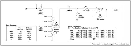
Related to posts #78 and #79, there seems to be disagreement about doing something as simple as hanging a pot off the front end. So I thought I'd show what actually happens.
Zin (input impedance) does increase as volume (input level) is decreased, but this has no practical effect--or if anything it could be considered beneficial.
In this case Pot1 is an input level vernier, or input level range adjustment, it has no application to this discussion.
.
.
Related to posts #78 and #79, there seems to be disagreement about doing something as simple as hanging a pot off the front end. So I thought I'd show what actually happens.
Zin (input impedance) does increase as volume (input level) is decreased, but this has no practical effect--or if anything it could be considered beneficial.
In this case Pot1 is an input level vernier, or input level range adjustment, it has no application to this discussion.
.
Attachments
Last edited:
Capacitance between conductors typically becomes an issue to be considered from about the top end of the audio spectrum, say 10kHz and up. The exact point depends on context, such as circuit impedance.bentsnake said:Capacitance between conductors is not usually a real-world issue unless you're working in the frequency band of, say, radar.
No conductor has zero capacitance. In the case of a piece of wire, it depends on how close are other conductors - probably mainly at the ends where it connects to something else.audiovisceral said:I think it is fair to expect 6" of straight 22 gauge hookup wire to be essentially 0 pF and thus noncontributable to the circuit?
I would try to explain rationale of using shielded cable for minimizing stray capacitance. Although not particularly relevant in this case since the length is relatively short (3"), simply I would like to share this technic.
There is always certain amount of parasitic capacitance from conductors connected to inverting node of the opmamp to surfaces connected to ground (housing, ground planes, power plains, etc...). Depending on circuit, certain value of this parasitic capacitance can affect stability.
If a component in NFB loop is placed on considerable distance, the lead from inverting node going to that component could add much parasitic capacitance. However if the lead is actually core of a shielded cable (e.g. flexible audio interconnect cable), the shield can electrostatically isolate it from surround if properly connected.
If shield is connected to GND the cable capacitance will actually add a lot of unwanted capacitance to GND. Not a proper way.
But if shield is connected to the output (or R4 in this case if it is low value resistor or short) the cable capacitance will just add to C2 (which is not a problem except in extreme cases) and will practically eliminate capacitive coupling from core to ground. Increased noise resilience is bonus.
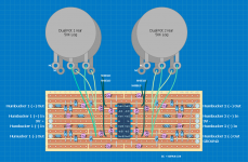
Okay. I tried putting together a stripboard schematic. I've attached it. I also tried implementing the shield-to-opamp-output technique you're describing. I'm not sure if I've done it right.
The thing I wonder is hypothetically if the shield picks up EMI noise and I dump that to the opamp output, aren't I just dumping the EMI noise into my audio signal?
Again, since the guitar cavity is shielded and we're talking just a few inches in each direction, can't I just use unshielded twisted 22 gauge hookup wire and be done with it?
If the attached makes better sense, I can still do that. It's just adding more work.
Can anyone proofread my layout? This is the third stripboard layout I've done and by far the most complicated. It looks like more than it is, but keep in mind each of the 4 quadrants are just copies of each other. Did I screw anything up?
Thanks.
Attachments
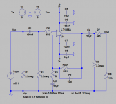
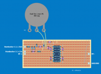
Here's just a single channel of the veroboard layout. Anyone care to tell me if I screwed anything up? In particular, I'm wondering if the way I laid out the 10 pF, 50K pot, and 5K resistor all connected through the - input and the feedback loop will work.
Thanks. 🙂
Thanks. 🙂
Attachments

Last edited:
The circuits OK although having both R6 and R8 is unnecessary. Make R6 something like 100k and take out R8.
Sorry. R8 is not actually part of the circuit. It was just to simulate the 10k impedance of the soundcard input. Should have removed that. Also just to clarify, you're saying my stripboard layout is good?
Thanks.
Thanks.
Also just to clarify, you're saying my stripboard layout is good?
Erm... I don't normally do stripboard 😛
Yes, as far as I can see it looks OK.
Also just to clarify, you're saying my stripboard layout is good?
For each unused op amp, connect its output to its inverting input, and ground the non-inverting input.
Connect the 10pF in the holes right next to the -in/out pins. Keep the pot leads very short.
Cut the unused part of the inverting input strip (past the connections) to minimize strays.
Exchange the positions of the 10uF and 100nF caps, or if possible install them both on the top ground strip.
Last edited:
- Status
- Not open for further replies.
- Home
- Source & Line
- Analog Line Level
- Critique this noninverting opamp buffer/amplifier please? Almost time to build...