looking at the datasheet, one can see that the 2k loading has a 0.8ppm THD, whereas the 600r loading shows 1.5ppm THD.
That tells us that the amp is capable of driving a 600r load, but is starting to show it is reaching it's "comfortable" limit.
The 1k in the feedback and the 2k+220r as non reactive loads, adds up to 689r for total loading on the opamp.
I consider that too low to be "comfortable".
Add on some parasitic capacitances and the opamp will distort more.
Raising the NFB resistance values slightly will help a lot.
Try R5=R4=2k, Rpot=20k, R3=220k, R6=2M2, C1=470nF, C4=47uF, C2=open circuit, or <=33pF
Can't argue with your reasoning on a technical level. I picked 2k as that is an oft quoted lower limit for a TL071/2 device and it was really just to highlight the possible LF rolloff caused by the 1uf output coupling cap under such conditions.
We are not disagreeing.
It's just we are trying to lead him/her through some of the thinking that is required to arrive at a reasonable chance of success.
It's just we are trying to lead him/her through some of the thinking that is required to arrive at a reasonable chance of success.
We are not disagreeing.
I realise that 🙂
Using the original values have you looked at what the peak currents from the opamp actually are, even with a 2k load and 1k feedback networks (pot at zero ohms). Its under -/+8ma, well within the capability of the device.
One real issue with the TL0 series opamps is that are not the best at swinging close to the rails under load when the rails are low to begin with... that is nothing to do with coming close to its peak output current, its just a characteristic of the device. The OPA134/2134 is much better in that regard.
Agh !!!!!
an open circuit in the feedback loop will momentarily take the opamp gain to it's maximum open loop gain, maybe 100000 times (+100dB)
That will output rail voltage virtual squarewaves to the next stage.
You must use a make before break, if you use a switcher.
The stepped attenuators have a continuous action. They don't break the circuit at any point in turning the knob. Read the eBay page linked. I have used these stepped attenuators before. They so not click or pop as you turn them due to the design.
I will implement the suggestions you, Mooly and bentsnake have made (many thanks) and also see if I can get that ltspice thing working and repost then.
Last edited:
...see if I can get that ltspice thing working..
Very good idea, since you obviously want to know what the heck's going on in there. Look on YouTube, lots of LTspice videos there.
Preliminary Tips: the toolbar is seldom used, most of the action is in the F keys, and in the right-click menu.
And, of course, the R (resistor), C (capacitor), and G (ground) keys.
Ctrl + R rotates a component.
.
Last edited:
...see if I can get that ltspice thing working...
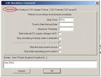
There's nothing "right" about these settings, only that they'll get you up and running. Right-click ~> Edit Simulation Cmd.
You have to provide settings for each circuit, but usually I save-as an existing circuit, which saves redoing the setup.
.
Attachments

Last edited:
We are not disagreeing.
Yes, well I am. All you're doing by driving these resistor values down is causing the feedback cap to grow to the point where an electrolytic is required. The surrounding impedances are such that they dwarf those in the feedback network and its noise contribution.
Last edited:
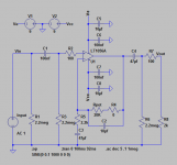
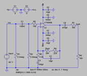
I've made a smattering of changes. I dig LT Spice. Very easy for drawing/editing schematics. Thanks for getting me initiated into that.
I attached what I have now (including decoupling caps). If it matters, the 9V+/- power will be travelling ~15 feet (through a 13 pin guitar cable) from the PSU to the buffer/amplifier board and these caps.
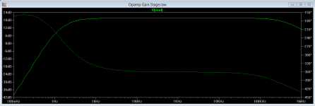
Simulation shows it with flat frequency response. Is there any way to check the distortion characteristics? I know it won't be exactly accurate since this is an LT opamp (and I'm using a Burr Brown), but still it would be nice to just test crudely that the design works. Same goes for noise floor.
What formula do I use to calculate the total load on the opamp like AndrewT was referencing? I want to make sure it is >2K to minimize distortion.
What is the point of increasing R6 so much (to 2M2)?
Lastly, I'm going into a soundcard with 10K input impedance. Should I change R8 to 10K then for accurate simulation?
Also thanks for pointing out I need R4 at 0 ohms (ie. removed) to enable 0 dB gain. Silly oversight. Fixed. Or would it be better for any reason to make R4 a negligable near zero number like 100 ohms just so there's always something there? I hope the 10 pF will still be fine in there with R4&Rpot at 0 ohms. Simulates fine with both of them at 0 ohms, at least for freq response.
Thanks guys for being patient with me.
I attached what I have now (including decoupling caps). If it matters, the 9V+/- power will be travelling ~15 feet (through a 13 pin guitar cable) from the PSU to the buffer/amplifier board and these caps.
Simulation shows it with flat frequency response. Is there any way to check the distortion characteristics? I know it won't be exactly accurate since this is an LT opamp (and I'm using a Burr Brown), but still it would be nice to just test crudely that the design works. Same goes for noise floor.
What formula do I use to calculate the total load on the opamp like AndrewT was referencing? I want to make sure it is >2K to minimize distortion.
What is the point of increasing R6 so much (to 2M2)?
Lastly, I'm going into a soundcard with 10K input impedance. Should I change R8 to 10K then for accurate simulation?
Also thanks for pointing out I need R4 at 0 ohms (ie. removed) to enable 0 dB gain. Silly oversight. Fixed. Or would it be better for any reason to make R4 a negligable near zero number like 100 ohms just so there's always something there? I hope the 10 pF will still be fine in there with R4&Rpot at 0 ohms. Simulates fine with both of them at 0 ohms, at least for freq response.
Thanks guys for being patient with me.
Attachments
Last edited:
thanks for pointing out I need R4 at 0 ohms (ie. removed) to enable 0 dB gain
No you don't. With R4 gone and Pot1 at zero you're in an unstable gain situation. Don't let the feedback resistor be smaller than the gain resistor (yet another rule of thumb--I really gotta write all these down someplace).
Yes I know I said the feedback resistors don't directly affect stability, but that was assuming some kind of vague adherence to the rules. Maybe the thumb rules, I dunno.
I don't mean to be smarty mouth, but you're now in the situation of a gosling following anything that moves. Too many cooks are making a hash of the stew. A very convenient example being post #28, which exactly contradicts several posts from before--posts you've altered your circuit to match.
When experts--assuming anybody is--disagree, what's a poor poster to do? Close your eyes and point, is what. Pick somebody, pick anybody, but pick and stick.
In my view you could do a lot worse than to go back to your schematic in post #1 of this thread, read and heed post #4, and stop right there. Bolt it together on the cheap and see what happens.
Hint: you'll like what happens.
ADDENDUM: ...er...except in that schematic, omit R6 and make C4 470uF. Rule: do not put filters in series unless you have good reason to do so.
.
Last edited:
Yes, well I am. All you're doing by driving these resistor values down is causing the feedback cap to grow to the point where an electrolytic is required. The surrounding impedances are such that they dwarf those in the feedback network and its noise contribution.
I am happy using any value of feedback pot: 10k/20K/50k/100k/250k are all available in the style attenuator I plan on using.
I would rather not use more lytics than I need for two reasons - they're physically large and from what I understand they just don't perform as well. Not sure if it matters in this location.
What feedback pot size would you suggest designing around for a target gain of ~10-12? (~20 dB)
...I would rather not use more lytics than I need...from what I understand they just don't perform as well....
Electrolytic capacitors in audio circuits. Did I mention experts disagreeing? Better pack a lunch, this will take a while.
.
Last edited:
Simulation shows it with flat frequency response. Is there any way to check the distortion characteristics? I know it won't be exactly accurate since this is an LT opamp (and I'm using a Burr Brown), but still it would be nice to just test crudely that the design works. Same goes for noise floor.
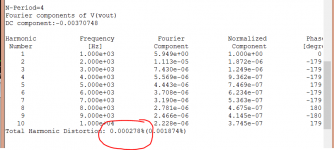
Looks like you are having fun 🙂 We can run a simulation of the distortion but unfortunately it doesn't tell us much simply because the opamp models do not exhibit the behaviour of a 'real' circuit made from all the individual transistors. The opamp models follows all the rules for an opamp and with some of the characteristics of the device chosen such as supply current and bandwidth.
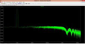
These show the distortion... to good to be true.
I would rather not use more lytics than I need for two reasons - they're physically large and from what I understand they just don't perform as well. Not sure if it matters in this location.
I guarantee that if listened to blind (no peeking) you wouldn't be able to pick a version with electrolytics vs one without.
We even did a test here (the files are long gone I'm afraid)
http://www.diyaudio.com/forums/everything-else/250147-listening-test-part-1-passives.html
Attachments
No you don't. With R4 gone and Pot1 at zero you're in an unstable gain situation. Don't let the feedback resistor be smaller than the gain resistor (yet another rule of thumb--I really gotta write all these down someplace).
Yes I know I said the feedback resistors don't directly affect stability, but that was assuming some kind of vague adherence to the rules. Maybe the thumb rules, I dunno.
The problem is with R4=R5, the minimum gain is 1 + 1 = 2 = 6dB. I want the minimum gain to be 0 dB or close to it. I can set R4 to say 220 ohms though as attached and if that improves stability rather than being 0 ohms in feedback that is fine. Frequency response seems fine that way.
you're now in the situation of a gosling following anything that moves. Too many cooks are making a hash of the stew.
In my view you could do a lot worse than to go back to your schematic in post #1 of this thread, read and heed post #4, and stop right there.
Maybe. But in fairness, I've been following your advice more than anyone elses. 🙂 I'm still glad others have others chime in, because I think there have been a lot of good points along the way. In particular, what caused a revision of most of the values was AndrewT's point in #21 that the total load to the opamp was ~689 ohms with the 10k pot, which was according to the spec sheet considerably increasing the distortion specs. I increased the pot to 20k as a result. (I'm still wondering if someone can provide the formula he used to calculate that though, so I can work out what it is now.) I also changed some caps as Mooly pointed out the filters were affecting the audio band.
There's been a striking amount of consensus. And I'm learning as we go. For example, I've now learned to do LT Spice drawings and frequency plots, which I probably wouldn't have learned otherwise. So from my perspective, I'm grateful for everyone's input.
In the end, the circuit I'm arriving at is basically along most of your suggestions. I just re-read your posts and took out that 100K (then 2M2) resistor to ground at the output which was as you said just there for a filter which was redundant.
Currently, the schematic plots razor straight frequency from 10 hz to ~80 khz. I'm wondering about the choices of cap size you suggested for C3/C4 though. I get an equally flat response going down to just 47 uF for both. Is it really a benefit using such large ones here?
Attachments

Last edited:
Your circuit is fine although I'd question C4 at 470uf if you are feeding into a 10k load.
Another practical point. When fitting electrolytics such as the feedback and output coupling caps, always actually measure the DC voltage across them when its all powered up. Offsets could go either way so fit the caps accordingly. The voltages are admittedly minute with a FET opamp but worth checking and doing.
Another practical point. When fitting electrolytics such as the feedback and output coupling caps, always actually measure the DC voltage across them when its all powered up. Offsets could go either way so fit the caps accordingly. The voltages are admittedly minute with a FET opamp but worth checking and doing.
Your circuit is fine although I'd question C4 at 470uf if you are feeding into a 10k load.
In what way would you question it? What would you be inclined to use here and why?
Another practical point. When fitting electrolytics such as the feedback and output coupling caps, always actually measure the DC voltage across them when its all powered up. Offsets could go either way so fit the caps accordingly. The voltages are admittedly minute with a FET opamp but worth checking and doing.
I read more of you discussing this topic here: http://www.diyaudio.com/forums/analog-line-level/265574-noob-question-electros-signal-path.html
So what you're saying is solder everything together minus the lytics, hook it to the power supply, and then measure across each of the electrolytic pads to see which orientation they should go (put the + on the positive pad, the - on the negative pad)? Honestly, it would probably be easier for me just to buy bipolar capacitors than be bothered with worrying about that if they will work as well. I'd really rather just solder it up and plug it in.
Also thanks for the distortion plot. Can you explain (or link to an explanation) that briefly says how you did that? What about noise floor plots? I imagine that would require entering detailed performance data on all the components like resistors and caps too which would be prohibitive.
Re: electrolytics being generally inaudible, I believe you. For me on this build it's going to be more an issue of size and buying the smallest decent ones I can.
Lastly, do you by any chance know how AndrewT calculated the total load on the opamp to be 289 ohms in #21? That would be useful formula for me right now just to see where I'm at...
Last edited:
The output pin feeds into the feedback and into the load.
These are both loads and are effectively in parallel.
Any cable parasitics are also in parallel.
1k for the NFB parallel to the series pair of 220r & 2k is calculated using the parallel resistor formula.
1/R = 1/R1 + 1/R2 +1/R... .... +1/Rn
1k||2220 = 689r441
These are both loads and are effectively in parallel.
Any cable parasitics are also in parallel.
1k for the NFB parallel to the series pair of 220r & 2k is calculated using the parallel resistor formula.
1/R = 1/R1 + 1/R2 +1/R... .... +1/Rn
1k||2220 = 689r441
The output pin feeds into the feedback and into the load.
These are both loads and are effectively in parallel.
Any cable parasitics are also in parallel.
1k for the NFB parallel to the series pair of 220r & 2k is calculated using the parallel resistor formula.
1/R = 1/R1 + 1/R2 +1/R... .... +1/Rn
1k||2220 = 689r441
Oh I see. You were calculating based on Mooly's #20.
Okay, so based on my most recent schem #34 (reattached here also), assuming a 10K input impedance of my soundcard input, my calculation is:
Series output: 10K (load) + 100 (R7) = 10100 ohms
In parallel with: A range of 220 ohms (R4) to 20220 ohms (R4+pot)
Gives: A range of 215 ohm to 6733 ohm opamp load
If I'm doing that right, that's a problem, because with the pot down to 0 ohms, my load is way too small (215 ohms). This problem can be solved by increasing the pot back to 100K, R4 to 2.2K, and R5 to 10k. But first I want to make sure I'm calculating this right.
Did I do that right? Also does R5 not figure in somewhere to this load calculation?
Attachments
Last edited:
Your circuit is fine although I'd question C4 at 470uf if you are feeding into a 10k load.
470uF is a convenient overkill value, I have no problem with using another.
Musicians often [always] find themselves in less than ideal working environments, which is why they all have large collections of adapters, trying to be able to plug anything into anything. Similarly, the 470uF value is intended as a "plug it into anything" number.
.
So what you're saying is solder everything together minus the lytics, hook it to the power supply, and then measure across each of the electrolytic pads to see which orientation they should go (put the + on the positive pad, the - on the negative pad)? Honestly, it would probably be easier for me just to buy bipolar capacitors than be bothered with worrying about that if they will work as well.
No you have to solder it together completely, including the, ahem, electrolytic capacitors. Then put a meter across each capacitor to check that you've correctly connected the positive lead of the capacitor to the most positive side of the circuit.
Things are rarely positive or negative unless you're talking about a battery. Commonly any given point is more positive, or more negative, than some other point.
Bipolars are fine. Some have been measured and found to have superior audio performance--but not all, so no telling.
Create a bipolar by soldering two, ahem, electrolytics together in series, positive to positive. BUT this cuts their value in half, so you have to double the capacitor values. For instance, two 470uF electrolytic capacitors in series give you a single 220uF result.
I personally use 50-volt, 105-degree electrolytics because I'm certain their more robust electrolyte has superior audio qualities. I will not thank you for confusing me with facts.
All of which reminds me to mention that there's no such thing as a gain of zero or one. It's unity gain.
.
- Status
- Not open for further replies.
- Home
- Source & Line
- Analog Line Level
- Critique this noninverting opamp buffer/amplifier please? Almost time to build...