470uF is a convenient overkill value, I have no problem with using another.
Musicians often [always] find themselves in less than ideal working environments, which is why they all have large collections of adapters, trying to be able to plug anything into anything. Similarly, the 470uF value is intended as a "plug it into anything" number.
.
To illustrate the extent to which 470uF is overkill at this position, it can feed e.g. 32ohm headphones down to 10Hz. Yet 32ohm is way beyond current capability of the opamp.
BTW there is no reason why R4 can not be 0. The rule of thumb you mention could possibly be applicable if the used opamp isn't unity gain stabile (not the case with OPA2134).
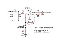
R6 prevents dangerous pops when plugging the interconnection cable while power is on. Value 2M2 is sufficiently high not to affect the LF limit which is mainly determined by the input impedance of the next stage (typically much lower than 2M2 so R6 contribution is negligible) and (of course) the value of above mentioned cap.
Last edited:
To illustrate the extent to which 470uF is overkill at this position, it can feed e.g. 32ohm headphones down to 10Hz. Yet 32ohm is way beyond current capability of the opamp.
Can you offer a substitute suggestion? 47uF? Less?
BTW there is no reason why R4 can not be 0. The rule of thumb you mention could possibly be applicable if the used opamp isn't unity gain stabile (not the case with OPA2134).
The problem I'm encountering is based on AndrewT's calculation formula for establishing the total output load on the opamp (see post #38). If R4 is 0 or near zero and the pot is turned to 0 as well, the output load of the opamp drops dramatically compared to the "ideal" of around ~2K+ and distortion rises.
Unless there is something incorrect about this calculation/reasoning in post #38. I suspect there must be but I'm not sure what. ie. If you set the feedback resistor as 1 ohms and turn the pot to 0 ohms, according to AndrewT's formula, the total load on the opamp becomes 1||10100 = 1 ohm, which would be well below the acceptable opamp limits. I don't get it.
R6 prevents dangerous pops when interconnection cable is connected wile power is on. Value 2M2 is sufficiently high not to affect the LF limit which is mainly determined by the input impedance of the next stage (typically much lower than 2M2 so R6 contribution is negligible) and (of course) the value of above mentioned cap.
So you would suggest putting that 2M2 R6 resistor at output back in to ground? If there is no harm and it will theoretically prevent pops, will do.
Attachments

Last edited:
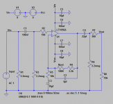
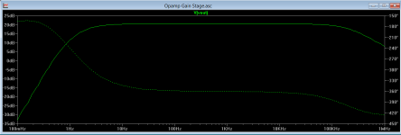
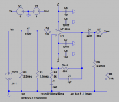
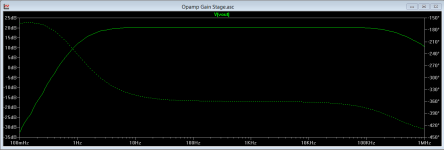
Currently, the schematic plots razor straight frequency from 10 hz to ~80 khz. I'm wondering about the choices of cap size you suggested for C3/C4 though. I get an equally flat response going down to just 47 uF for both. Is it really a benefit using such large ones here?
OK so you're not a gosling. Shows what I know.
Seeing flat frequency response in LTspice is to be expected. Partly because, as Mooly pointed out, the op amps are generic, but mainly because, as I've pointed out 50,000 times, the engineers have handed us excellence on a silver platter, all we have to do is not screw it up.
Op amps are not just for audio. They do, in fact, amplify through the ultrasonic and beyond. This is one reason for C2.
However, no need to fixate on this because they only amplify what comes in.
C4: See post #39 above.
C3: I don't blame you for not remembering by now, but the value in the schematic is yours, not mine...or it might be somebody else's entirely. In any case it, like C4, is an overkill value, intended to deal with any resistor network that might conceivably be connected. And I'm not aware that anybody has yet decided what that resistor network might be. At this point I vote for just making the whole feedback network in the 50k range. But I also vote that it doesn't matter...as long as nothing is less than 2.2k.
When a decision is finally made, do NOT cut the value C3 anywhere near close. Remember that components have tolerances, and tolerances change with temperature. The rule in electronics is to always leave yourself some slack, more is better.
My vote: do not omit C3. And by the way don't change R1 and/or R3.
.
R6 prevents dangerous pops when plugging the interconnection cable while power is on.
It does? That's a new one on me, I must admit.
However, since the following amp is near-certain to be AC coupled, it also connects two same-frequency-range filters together in series, which violates the x10 rule.
(for a change, not a rule of thumb, a real engineering rule)
.
OK, I had a search around, it seems guitar output impedances run as low as 6k at some settings, although they're frequently higher. I was a bit surprised, I thought they were typically higher than that.
Of the values you suggest I'd use 10k to ground with 100k pot. This will leave your cutoff down around a ~16 Hz with a 1u cap. A bit high for hi-fi, but fine here.
Why? The general rule is that when the pot (feedback) in parallel with the resistor to ground are equal to the source impedance, then the thermal and current noise contributions of the feedback network are equal to those of the source impedance. So your guitar can be 10k or a bit below (typical low end) and these parts of the circuit will only contribute roughly the same noise.
In the worst case it will double the noise, but the noise from the pickup will dominate in the case of higher impedances. Pickup noise is not usually an issue and the added noise here is unlikely to prove so. The total noise can be no lower than the source noise * amp noise gain. Here's how to calculate the noise contributions of the various elements:- http://www.analog.com/static/importe...als/MT-049.pdf
Use a TL071, forget C2.
The loading will be >2k. By inspection.
Yes, electrolytics have limited life, they require using the right way round, and they have higher-than-most distortion unless you make them grossly oversize. Not that distortion is likely to be an issue, even expecting a clean sound, it's guitar, not hi-fi. I just think it's easy not to use one here, so why bother agonizing about it. Sidestep any debate, so-to-speak.
It does? That's a new one on me, I must admit.
However, since the following amp is near-certain to be AC coupled, it also connects two same-frequency-range filters together in series, which violates the x10 rule.
(for a change, not a rule of thumb, a real engineering rule)
.
Instead blindly sticking to rules (applicable just in certain circumstances) better check with LTSpice the effect of R6. Freq response with R6=2M2 and R6 removed when the next stage is AC coupled 47k for example. Do you see any loss in LF?
.
The only way I know to change a non-inverting gain circuit into a buffer.
.
It's pretty basic. Unity gain buffer AKA voltage follower is made by simply connecting output to inverting (-) input. In this case unity gain is achieved when Rpot=R4=0 in which case R5 C3 branch becomes just a load connected to output.
Can you offer a substitute suggestion? 47uF? Less?
The problem I'm encountering is based on AndrewT's calculation formula for establishing the total output load on the opamp (see post #38). If R4 is 0 or near zero and the pot is turned to 0 as well, the output load of the opamp drops dramatically compared to the "ideal" of around ~2K+ and distortion rises.
Unless there is something incorrect about this calculation/reasoning in post #38. I suspect there must be but I'm not sure what. ie. If you set the feedback resistor as 1 ohms and turn the pot to 0 ohms, according to AndrewT's formula, the total load on the opamp becomes 1||10100 = 1 ohm, which would be well below the acceptable opamp limits. I don't get it.
If we ignore capacitors for awhile (reasonable approximation within audio band) impedance seen by opamp output is:
R = (R4+Rpot+R5) || (R7+R8)
If R4=Rpot=0 => R = R5 || (R7+R8)
This means R5 becomes just another load connected to output, parallel to R7 + R8. So R seen by the output is close to 2k in above case.
Can you offer a substitute suggestion? 47uF? Less?
I would advise you to check freq response in LTSpice with various values. I guess acceptable response is achievable with values between 2u2 - 47u, depending how low you want to go, decide by simulating in LTSpice.
Instead blindly sticking to rules (applicable just in certain circumstances) better check with LTSpice the effect of R6. Freq response with R6=2M2 and R6 removed when the next stage is AC coupled 47k for example. Do you see any loss in LF?
I advise against cascading similar filters. Keyword: advise. Suit self.
.
OK, I had a search around, it seems guitar output impedances run as low as 6k at some settings, although they're frequently higher. I was a bit surprised, I thought they were typically higher than that.
Of the values you suggest I'd use 10k to ground with 100k pot. This will leave your cutoff down around a ~16 Hz with a 1u cap. A bit high for hi-fi, but fine here.
Why? The general rule is that when the pot (feedback) in parallel with the resistor to ground are equal to the source impedance, then the thermal and current noise contributions of the feedback network are equal to those of the source impedance. So your guitar can be 10k or a bit below (typical low end) and these parts of the circuit will only contribute roughly the same noise.
In the worst case it will double the noise, but the noise from the pickup will dominate in the case of higher impedances. Pickup noise is not usually an issue and the added noise here is unlikely to prove so. The total noise can be no lower than the source noise * amp noise gain. Here's how to calculate the noise contributions of the various elements:- http://www.analog.com/static/importe...als/MT-049.pdf
Thank you very much for the insight on that. That provides a good guiding principle for selecting my values.
FYI, the humbuckers I'm working with spec around 16.9 K for bridge and 9.6 K for neck pickups. I'm not sure if it matters, but I think those readings are generally measured across the + and - humbucker terminals. ie. It's the total impedance across the whole pickup. I'm actually sending the + and - terminals from each humbucker to their own buffers independently. (I am maintaining fully balanced output from the humbuckers by buffering each + and - independently and sending each out through a different pin in the 13 pin guitar cable, eventually reaching the balanced input of my soundcard).
So I'm not sure if each buffer will see only half that rated impedance. 😕 This would be an important point to clarify if possible. If that means each buffer sees 8.4K and 4.8K I'll drop R5 to 5K and use a 50K pot instead. I think this is the case. I just measured a pickup I have sitting around. When I measure that one from + to - I get 15.6K (what it's rated as). When I measure from + to where the blue arrow indicates in the below diagram at the two wires tied together, I get 7.8K. If each + and - has it's own buffer, that's what each would see, right?
Numerous people have now told me to get rid of C2. Huh. If it offers any theoretical stabilization effect I'd rather keep it. I cut it to 5pF to maintain freq response. I'm not sure if this is getting silly now... Sorry if it is.forget C2.
Okay but this is the part I'm still curious about. If AndrewT is right, the formula for calculating opamp loading is:The loading will be >2k. By inspection.
load = [10K (input impedance of sound card) + R7] || [R4 + pot]
I'm still operating on the presumption this is correct as no one has corrected it. I've therefore set my values accordingly to ensure even when the pot is at 0 ohms, I'm getting a minimum of 1.8k loading based on this calculation with the attached schematic.
It's also still razor flat from ~10hz up to 20kHz. Unfortunately I'm needing lytics to keep the frequency flat, but I'll just get some nice Nichicon bipolars to save me the trouble of orientation. I can live with that. I'd rather not start losing bass to any degree, as I will be using this circuit with downtuned guitars and bass guitars too.
Also this may seem irrational but I increased the R7 output resistor back to the original 560. I don't know how much the value really matters, as no one has commented too much on it. I don't know how much parasitic capacitance a 13 pin 15 foot guitar cable produces (or how to calculate that effect on the circuit). I just know a good well proven guitar buffer schematic uses this value. Even if it's "overkill", if it doesn't hurt, and it works, then I am happy with that.
Attachments
Last edited:
.
Things are not nearly confused enough around here. There hasn't even been a fistfight yet. Sooo...
Does impedance, to a degree, really matter ? [Archive] - Mandolin Cafe Forum
.
Things are not nearly confused enough around here. There hasn't even been a fistfight yet. Sooo...
Does impedance, to a degree, really matter ? [Archive] - Mandolin Cafe Forum
.
Okay but this is the part I'm still curious about. If AndrewT is right, the formula for calculating opamp loading is:
load = [10K (input impedance of sound card) + R7] || [R4 + pot]
I'm still operating on the presumption this is correct as no one has corrected it. I've therefore set my values accordingly to ensure even when the pot is at 0 ohms, I'm getting a minimum of 1.8k loading based on this calculation with the attached schematic.
No. The load in your last diagram (component designations may have changed) is:-
load = [10K (input impedance of sound card) + R7] || [R4 + pot] + R5
AndrewT is rarely flatout wrong, I think this is just crossed wires.
As regards the impedance of the humbuckers, I think you're right. So these are the first things the pickup sees. I wasn't sure if you had vol and tone controls first.
Last edited:
No. The load in your last diagram (component designations may have changed) is:-
load = [10K (input impedance of sound card) + R7] || [R4 + pot] + R5
AndrewT is rarely flatout wrong, I think this is just crossed wires.
As regards the impedance of the humbuckers, I think you're right. So these are the first things the pickup sees. I wasn't sure if you had vol and tone controls first.
It's
load = [10K (input impedance of sound card) + R7] || [R4 + pot + R5]
No. The load in your last diagram (component designations may have changed) is:-
load = [10K (input impedance of sound card) + R7] || [R4 + pot + R5]
That makes way more sense. Thank you. That's what I was asking earlier. I figured R5 had to fit in there around that point.
Keeping in mind that we've established the OPA2134/OPA4134 series is unity stable, and we don't need R4, I've removed it. I think the 5 pF cap is still okay in there even with pot to 0. Freq response is fine either way at least.
Attached circuit opamp load with correct calculation now ranges from 3393 to 8859 ohms. All good.
As regards the impedance of the humbuckers, I think you're right. So these are the first things the pickup sees. I wasn't sure if you had vol and tone controls first.
If I'm right, then each of the + and - neck humbucker buffers will see 4.8K and each of the + and - bridge humbucker buffers will see 8.45K. (Would be great to have further confirmation of this if anyone knows for sure.)
I think the closest match I can go with is 5K on R5 then. If I understand your post, then in this case the bridge humbuckers will create more noise than the buffer/amplifier circuit, and the buffer/amplifier circuit will create (slightly) more noise than the neck humbuckers.
All close enough to be hopefully happy? I suppose I could match R5 exactly to each pickup ... But maybe that's just being silly? Maybe close enough is close enough? I don't know how much this actually matters in terms of the noise floor and dB. Maybe we're just splitting theoretical hairs. Is there any way to actually estimate the significance or noise floor from this?
Also to answer your implied question, there are going to be no volume pots (besides the ones in the feedback loops) or tone pots on this guitar setup. It's a wiring/electronics design purely for recording balanced guitar output direct to DAW. Humbucker > Dual (balanced) buffer/amplifier > sound card.
Attachments
Last edited:
I advise against cascading similar filters. Keyword: advise. Suit self.
.
But they are not similar in value. If C4=10uF for example the corner freq is f=1/(2*pi*10uF*2M2) which is 0.008Hz. Negligible effect in audio band.
Yet precisely this high pass created by adding this 2M2 resistor will prevent mentioned unpleasant pop in case opamp develops significant DC offset for some reason.
For the sake of stability keep all leads connected to inverting input as short as possible. Take care to keep R5 and Rpot as close as possible to the pin.
For the sake of stability keep all leads connected to inverting input as short as possible. Take care to keep R5 and Rpot as close as possible to the pin.
Duly noted. Rpot is going to be a problem for that, though. Rpot will be connected to the stripboard circuit by ~3" 22 gauge wire leads in order to be mounted to the guitar body for control. Close enough still I presume. How much can 6" of 22 gauge wire affect this?
I guess part of the answer to that (and how effective this circuit will be) is: How much capacitance is 6" of 22 gauge stranded/solid core wire? I just jammed a ~6" length of wire into my multimeter and it's reading 0 pf...
Last edited:
- Status
- Not open for further replies.
- Home
- Source & Line
- Analog Line Level
- Critique this noninverting opamp buffer/amplifier please? Almost time to build...