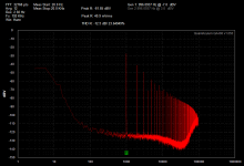
Just to show the effect of some cables -- the shielded twisted pair is with some Belden and a Neutrik XLR, it sits right on top of the baseline for the analyzer.
Pomona 3787 is a 36 inch BNC to "Grabber" and the B&K scope probe is run of the mill standard. The Textronix cable is much longer than the others so can be forgiven somewhat.
I don't have the QA cables, gave 'em away.
Thanks Jackinnj!
I think there is another problem with the way I am trying to acquire the signal with the alligators on the speaker wire. The wire is a flat braided type, and probably attracting noise. I moved one further from a power cord, and the THD dropped to 1/4 of the previous measurement.
I think the grabbers would be ideal for input to the DUT, but I am not sure what will be best for the output from the DUT -- I have to use alligators, as that's what is on the QA190.
There has to be a way to get the test signal bigger... The peak is some 40db below full scale, which isn't that much above the noise...
When testing THD, the output at 0 dB is approx 0.75 Volts peak. I believe this is set at calibration time.
Depending on the unit the "sweet spot" for amplitude appears to be between -6dB and -10dB below "0".
The other thing is, are you measuring the amplifier's output?
If so, is there any reason you are not or have not tried the QA400 "direct" with a suitable voltage divider to knock the level down to where it is safe to input to the QA?
I'd like to see how that compares.
Again, not sure what ur measuring exactly. Sorry, since I don't have the diff input box, "it's greek to me!"
I do NOT understand the manual re: dBV input and output gains. The manual never once refers to what happens here, nor does it identify the gain that input/output gain controls. The diagram refers to Tx and Rx.
Do the external gains refer to an amplifier between the device under test and the analyzer? I am testing an amp with 15 dB gain, using a QA190 set to /10.
What values should I put in the dBV dialog box?
Do the external gains refer to an amplifier between the device under test and the analyzer? I am testing an amp with 15 dB gain, using a QA190 set to /10.
What values should I put in the dBV dialog box?
When testing THD, the output at 0 dB is approx 0.75 Volts peak. I believe this is set at calibration time.
The QA400 measures in dBFS, dBV or dBr. If the dBV is selected then 0dB is 1Vrms ~ 1.414Vp.
The calibration level is 1.27Vrms FS.
As Bear pointed out the best result is at about -10dBV with a direct signal to the input.
Your SNR will improve with a larger input signal.
I do NOT understand the manual re: dBV input and output gains. The manual never once refers to what happens here, nor does it identify the gain that input/output gain controls. The diagram refers to Tx and Rx.
Do the external gains refer to an amplifier between the device under test and the analyzer? I am testing an amp with 15 dB gain, using a QA190 set to /10.
What values should I put in the dBV dialog box?
No the gain does not refer to the gain of the amplifier. QA is referring to gain in dBV. Referenced to 1Vrms (0dBV)
Depending on the unit the "sweet spot" for amplitude appears to be between -6dB and -10dB below "0".
The other thing is, are you measuring the amplifier's output?
If so, is there any reason you are not or have not tried the QA400 "direct" with a suitable voltage divider to knock the level down to where it is safe to input to the QA?
I'd like to see how that compares.
Again, not sure what ur measuring exactly. Sorry, since I don't have the diff input box, "it's greek to me!"
Yes, I am measuring amp output. Can you recommend values for an appropriate voltage divider?
It appears that with 0.75 V output from analyzer, and 15 dB amplifier gain, that a ladder with 33 on top and 10 on bottom would be ok. Definitely need the grabbers on the BNC cable now.... will get some tomorrow.
No the gain does not refer to the gain of the amplifier. QA is referring to gain in dBV. Referenced to 1Vrms (0dBV)
I'm sorry, I don't understand what you are saying here. I really don't know what to put in that dialog box. Can you give me a reference to read so I know what you mean?
From the help window, it sure looks like the gains are the amp gain and the QA190 attenuation.
I do NOT understand the manual re: dBV input and output gains. The manual never once refers to what happens here, nor does it identify the gain that input/output gain controls. The diagram refers to Tx and Rx.
Do the external gains refer to an amplifier between the device under test and the analyzer? I am testing an amp with 15 dB gain, using a QA190 set to /10.
What values should I put in the dBV dialog box?
The extra gain feature rescales the display. Avoid using this feature until you absolutely understand it. It's better to stay referenced to 0dBV.
/10 or 1/10 is a ratio of 0.1, referenced to dBV is 1/10 = 100mVrms which is -20 dBV.
20*Log(0.1).
Your amplifier has a gain of 15dB. The gain is ~ 5.623. If you input 1Vrms then your output from your amplifier is 5.623Vrms or 15dBV. Your probe is set to divide by 10. Therefore 5.623Vrms/10 = 0.523Vrms.
20*Log(0.5623) = ~ -5dBV.
20*Log(0.5623) = ~ -5dBV.
Got it, THANKS.
So for a peak output of 0.75 V ( which is the test tone peak ) a 15dB gain results in a peak voltage of about 4.2 volts. Selecting /10 makes this a peak of 0.42 volts, which would be displayed as about -7.5 dBV? Or does the analyzer use the 0.75 volts as the input and display 20*log(0.42/0.75) = -5 dBV?
At any rate, the display is clearly showing well under those values. So the differential probe is not reading the output of the amp as 4.2 volts. It is clamped onto the insulated speaker wire, as suggested by the manual.
It must be reporting a *significantly* lower value.
Got it, THANKS.
So for a peak output of 0.75 V ( which is the test tone peak ) a 15dB gain results in a peak voltage of about 4.2 volts. Selecting /10 makes this a peak of 0.42 volts, which would be displayed as about -7.5 dBV? Or does the analyzer use the 0.75 volts as the input and display 20*log(0.42/0.75) = -5 dBV?
At any rate, the display is clearly showing well under those values. So the differential probe is not reading the output of the amp as 4.2 volts. It is clamped onto the insulated speaker wire, as suggested by the manual.
It must be reporting a *significantly* lower value.
If you input -7.5dbV QA400 will display just that. That is assuming the QA was properly calibrated. If it doesn't display this then something is wrong. If extra gain is set in QA400 "extra Gain" is displayed on the plot. if there is no extra gain set and you read something different. The the QA is not calibrated properly. Keep in mind a differential probe measures the exact potential across the points the clips are attached to. You may not be getting the voltage you're expecting. Confirm the voltage at your speaker leads with another meter if you have one.
Got it, THANKS.
So for a peak output of 0.75 V ( which is the test tone peak ) a 15dB gain results in a peak voltage of about 4.2 volts. Selecting /10 makes this a peak of 0.42 volts, which would be displayed as about -7.5 dBV? Or does the analyzer use the 0.75 volts as the input and display 20*log(0.42/0.75) = -5 dBV?
At any rate, the display is clearly showing well under those values. So the differential probe is not reading the output of the amp as 4.2 volts. It is clamped onto the insulated speaker wire, as suggested by the manual.
It must be reporting a *significantly* lower value.
If you're using the clamp then you're measuring current. I'm not sure what you mean by peak. Is this referring to the maximum output of the generator? If so please use another word or phrase. We reserve the word peak to mean Vp which is different than a maximum of 0.75Vrms.
What exactly is it that you are trying to measure?
The current clap of the 190 is intended for measuring power factor of AC mains and high power audio amplifiers. QA says for ever 10A the probe outputs 1V.
Your amplifier will have to have significant power output and be driven hard to get 10A and it has to be connected to a load. You will get next to nothing if the amplifier is not loaded.
I think a direct connection to the speaker output of your amplifier will give you a lot more information.
If you're using the clips they don't clip onto the insulated speaker leads. They clip onto the conductive wire of the speaker leads. The manual is referring to the current clamp to be clamped on the insulation of the speaker leads. Are you confusing the two?
The current clamp is is a great feature but its far from linear to the point where its useful for distortion measurements. It may also be a significant hum detector. It does have extended bandwidth.
In the plots there is a lot of 60 Hz noise. Way more than I would expect. Does it go away when the inputs to the probe are shorted?
If time and confusion permit I'll try a similar setup tomorrow and see what I get. The amps gain seems really small. Usually a power amp is at least 20 dB. 29 dB is the THX standard.
A general question concerning the QuantAsylum QA400.
Does it have any benefit(s) over a sound card of 24/192 with AD SNR 109 dB RMS unweighted and DA SNR 110 dB RMS unweighted?
Any reply?
- Home
- Design & Build
- Equipment & Tools
- QuantAsylum QA400 and QA401