A general question concerning the QuantAsylum QA400.
Does it have any benefit(s) over a sound card of 24/192 with AD SNR 109 dB RMS unweighted and DA SNR 110 dB RMS unweighted?
Does it have any benefit(s) over a sound card of 24/192 with AD SNR 109 dB RMS unweighted and DA SNR 110 dB RMS unweighted?
Try the clip lead trick. You are getting a lot of 60 Hz so its probably electrostatic coupling. making sure you have a good common reference even with the differential probe will help. if you have a strong signal it can cause the fundamental to clip and seem distorted even if it isn't. You can look for the hum by muting the test tone and looking at what is coming out with no signal. Another possibility is power supply modulation when the amp is under load.
How?
The cap banks in these amps are stupidly large. I don't see modulation of the PS being an issue.
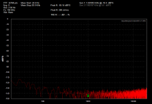
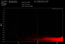
OK so here is the symptom. Measurements with the QA400 distortion analyzer and QA190 differential probe clamped via alligator clips on the speaker cables.
These are the distortion results testing an F5Turbo at 48KHz sampling rate, -10 dbFS and /10 on the qa190:
16K: 0%
8K : 0.019%
4K : 0.026%
2K : 0.014%
1K : 0.05% -- AND WHEN SIGNAL IS REMOVED THERE IS AN ECHO OF THE 1kHz SIGNAL!!!
What I mean by echo is that the QA400 applies a test tone to the unit in short bursts. The echo is that of the test tone burst starting and stopping, and eventually fading away.
The cap bank is 88,000uF per polarity per channel, arrange as CRC with R=0.1 Ohm.
Does the QA400 try to mute the output on stop and then some time later stop generating the signal?
I can't see this being about the DUT, because this is an echo of the test tone, repeating itself, not feedback/oscillation.
Last edited:
The test tone is 'windowed" by the QA400. Its part of the system design. When its "muted" it should be very low. Try a loopback test on the QA400 itself and see how much is coming out.
Test setup is very important and its well worth taking some time to remove external confounders so you can see what is happening in the test system.
I usually start testing this way-
Set up the test.
Do not connect the test source to the DUT at this time.
On the diff probe, short the leads together and get a baseline. with them not connected to anything else.
Then with the leads shorted connect them to the chassis of the DUT. This will show if there is enough common mode to cause errors in the measurement.
Then connect to the DUT with the power off. This will show leakages from the power transformer and power filtering that could cause problems.
Then power on with the DUT input shorted, this should show how much output is from internal noise.
The connect the QA400 ground to the DUT with the DUT inputs shorted. This will show if significant ground currents between the two boxes are affecting the measurements.
There are a lot of steps to validating a measurements setup. if you go through this a few times you start learning where artifacts come from and how to fix them so you can see what is coming from the DUT.
USB communicates at around 1 KHz so if you are getting noise from the USB into the test setup it will be at 1 KHz + harmonics.
One very big problem with really large filter caps is the short conduction angle. It means that the caps charge very quickly with large current spikes. If the caps are mismatched there will be significant 60 Hz spikes. If they are closely matched the 60 Hz component will be minimized. You can see this directly using the current clamp that came with the QA190. You need to clamp it around one leg of the AC.
Thanks Demian. When I am doing all of this, what settings should be used on the QA400? They don't seem to refresh without testing *something*.
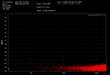
QA400 connected to DUT via speaker wires. Input via BNC to RCA adaptor. power to DUT OFF. /100
Attachments
Last edited:
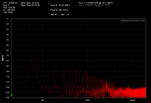
Load changed from speaker to 10R resistor. /100
Attachments
Last edited:
Hi Big E,
I've been doing some testing over on the HP339a thread
with the same stuff that you have.
There is more than meets the eye with this stuff.
Demian is very good at this stuff as well as some
other's here, so your in good hands.
I've got a lot of plots towards the end and also
in my gallery.
Take these for what they are worth:
What I've found when making measurements and to show people
what I'm doing is to include the QA400 interface (on the right side
of the screen) for the first measurement.
When making adjustments to see the result I keep the points pretty
low, 2000 - 8000 points and minimal average AVG...2, 4, 6, 8 points.
It let's me get a feel for what is happening.
Then when I'm taking the actual measurement I up the points to about
30K and set AVG to 30, 40 or 50. Then I let it settle down and do a
screen print (Print Screen button) or a window print (Alt + Print Screen).
We've generally agreed to use the Flat Top window for general measurements
and post comparisons. For looking as noise/distortion close to the fundamental I use the Hann window because It seems to lower the noise floor
a bit more and the harmonics and distortion stand out more.
Don't worry about making mistakes or errors, or posting them, this stuff
is a process and we just have to get our hands dirty. Just don't kill yourself, that is bad kharma. Other people learn from our mistakes too, so in the end,
we all end up with better products, projects, DIY stuff etc.
A typical Eastern response might be to leave our ego behind.
A typical Western response is to have fun. : )
DEMIAN, Thank's for posting how to check out the QA190 with
the QA400. I kinda figured that out, but it took me a few funny
plot postings to know.

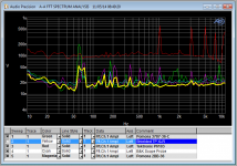
Just to show the effect of some cables -- the shielded twisted pair is with some Belden and a Neutrik XLR, it sits right on top of the baseline for the analyzer.
Pomona 3787 is a 36 inch BNC to "Grabber" and the B&K scope probe is run of the mill standard. The Textronix cable is much longer than the others so can be forgiven somewhat.
I don't have the QA cables, gave 'em away.
Pomona 3787 is a 36 inch BNC to "Grabber" and the B&K scope probe is run of the mill standard. The Textronix cable is much longer than the others so can be forgiven somewhat.
I don't have the QA cables, gave 'em away.
Attachments
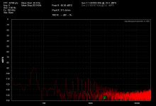
I cannot seem to get the harmonic THD spikes out of the grass. I need them to stand proud so that I can set their relative values in real time. Is there any way to do that?
Thanks.
Thanks.
I cannot seem to get the harmonic THD spikes out of the grass. I need them to stand proud so that I can set their relative values in real time. Is there any way to do that?
Thanks.
Add a small amount of averaging just enough to get the noise down but with reasonable response. Otherwise it requires a lot of Patience. Tweaking and waiting for a result.

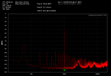
F5Turbo results are all wrong. I think I have to measure in the same location, and with the other channel completely disconnected.
This is not as easy as I thought it would be.
This is not as easy as I thought it would be.
Can you increase the number of averages?
Yes, I have one with 32.
Attachments
- Home
- Design & Build
- Equipment & Tools
- QuantAsylum QA400 and QA401