When using an RCA to BNC does it matter if it the connector has 75 ohm characteristic impedance or 50 ohm?
@roberts67, Welcome and glad you are fooling around with this.
It's right up my alley that I'm interested in doing with some of
my gear too.
Now you got me thinking about doing the same with the Dynaco that
I have. It is the ST70 Series II. Would be interesting to compare
you mods to the stock reissue.
Wondering what you source oscillator is and what level input to
amp? What is your tube compliment brand etc? Bias set point?
If you have pics of your amp please post them as I and other
DIYers would benefit from it. Also your set up too.
It gets fun when others come in here with their projects and interests.
There are a lot of really good folks with a lot of knowledge and we
all benefit.
I don't have a differential probe... wondering what to do to make one?
Doable project here I would imagine...is there a repurpose box for one?
Differential probe- You can build one but for the price the QA190 can't be beat: QA190 Differential Probe
Thanks Demian.
Maybe you guys can answer this for me. What is the best way to
measure an amp? Direct? or Through Differential Probe?
Or run it through the HP 339a then to amplifier?
or from HP339a, then amp, then Distortion meter of HP 339a,
then to the FFT.
From oscillator
. A to amp
. B to load
. C from load before splitter
.. after splitter
... D to distortion meter
... E to FFT
I can play around with it but just don't want to fry everything
going through the process.
The 339A has a significant 2nd H spike in it's filter amp which passes to the output and limits THD measurement to roughly 0.001% distortion, depending on a few alignment and parts factors, so if the amp is ultra high performance, then using the 339 will not be such a good idea. If you're looking primarily at tube amps, then by all means use the 339 as an analyzer and look at the output with the QA400 or equivalent -- you'll see the harmonic structure of the output signal very clearly. The QA diff probe can be a real asset with tube gear...
Differential probe- You can build one but for the price the QA190 can't be beat: QA190 Differential Probe
Not available in Canada?
Hello!
The ST-70 has a new home. I left it stock, used JJ E34L tubes and standard bias point. I have been playing around with the QA400 on a Fisher X100-3 using some suggested tweaks here and seem to be getting better measurements now. For an oscillator I am using the signal out from the QA400. Hopefully I am not missing something here. I bought the QA190 differential probe and use that as my interface set at the 10X mode. I measure across a 200 watt 8ohm dummy load. I want to do power measurements with the QA400 and QA190 with supplied software but don't think that is an option. Am I just using ohms law here or does the QA400 software do this someplace?
The ST-70 has a new home. I left it stock, used JJ E34L tubes and standard bias point. I have been playing around with the QA400 on a Fisher X100-3 using some suggested tweaks here and seem to be getting better measurements now. For an oscillator I am using the signal out from the QA400. Hopefully I am not missing something here. I bought the QA190 differential probe and use that as my interface set at the 10X mode. I measure across a 200 watt 8ohm dummy load. I want to do power measurements with the QA400 and QA190 with supplied software but don't think that is an option. Am I just using ohms law here or does the QA400 software do this someplace?
Screen Shots
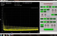
Here are my screen shots for THD on the recapped Fisher X100-3 integrated tube amp. The 2nd picture is the right channel even though the setting says left. I am going out of the QA400 into the auxiliary input of the integrated amp. The amp is going into a 8 ohm dummy load. I have the voltage clamps from the QA190 clipped across the dummy load with 10X setting and then going into the input of the QA400. I changed the average to 10 as suggested by someone else here. Hopefully I am on the right track. I come from a non-technical background and do this for fun. I am not looking for super accurate results, but would be happy to be within .01 accuracy with my measurements.
Here are my screen shots for THD on the recapped Fisher X100-3 integrated tube amp. The 2nd picture is the right channel even though the setting says left. I am going out of the QA400 into the auxiliary input of the integrated amp. The amp is going into a 8 ohm dummy load. I have the voltage clamps from the QA190 clipped across the dummy load with 10X setting and then going into the input of the QA400. I changed the average to 10 as suggested by someone else here. Hopefully I am on the right track. I come from a non-technical background and do this for fun. I am not looking for super accurate results, but would be happy to be within .01 accuracy with my measurements.
Attachments
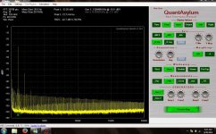
It looks like you still have a common mode issue with the hum harmonics across the bottom. Several steps for figuring that out-
1) short the two clips together not connected to anything else, look at the baseline. it should be pretty free of junk.
2) with the clips shorted, connect them to the chassis/ground of the device under test (DUT) it should still be a flat line. if there is hum then there is significant common mode between the DUT and the Test computer.
3) Tie a cable from the QA400 chassis or the computer chassis (the shield of the USB cable for example) to the chassis of the DUT and see if the hum drops. I find this needs lots of experimentation to find the lowest noise places to make the connections.
4) If the noise goes away when the probes are shorted and connected to the chassis ground but not when connected to the load its possible the hum is power supply related. Try changing the level at the QA400 output and see if the hum goes down with level. That would mean that the supply is coupling its ripple from load current into the audio path.
5) If the hum does not change disconnect the output from the QA400 and short the input to the amp. If this reduces the hum there still is a common mode problem per above and grounding /supply isolation is the next task, if you are using a laptop, run it on batteries and disconnect the ac adapter.
Looking at the pictures it seems the power supply has a lot of ripple, you can see sidebands on the audio (I'm guessing +/- 120 Hz from the 1 KHz fundamental). These are from AM modulation from the ripple on the output. They would come from rectifier/cap/grounding getting into the audio stream. Following the current loop will show where its sharing grounds with audio signals etc. I see these problems even in very carefully designed instruments and sometimes cutting a trace and rerouting a ground will reduce the effects by 20-40 dB.
The hum signals are about what I would expect from an ST-70, maybe just a little high. I don't remember the S/N spec, but around 80dB would be about right.
The ST-70 is not grounded to power line ground through the AC line cord, so it is floating relative to computer chassis ground.
Demian's suggestions are good ones, particularly running a laptop on batteries for the testing if possible.
The ST-70 is not grounded to power line ground through the AC line cord, so it is floating relative to computer chassis ground.
Demian's suggestions are good ones, particularly running a laptop on batteries for the testing if possible.
Hello
Hello Damian! Thanks for taking the time to respond. The Fisher has found a new home, but I will play around with the settings and grounding as suggested and report back on my next project. Thanks for keeping this fun! Good to know I still need to tweak my set-up. Robert
Hello Damian! Thanks for taking the time to respond. The Fisher has found a new home, but I will play around with the settings and grounding as suggested and report back on my next project. Thanks for keeping this fun! Good to know I still need to tweak my set-up. Robert
QA400 Balanced In/Out Interface
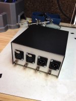
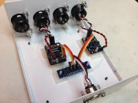
Just thought I would share this little project I've been working on. It's a two channel BNC to XLR (and vice versa) converter based on THAT 1646 and 1206 ICs.
My intended use is for connecting the QA400 to a mixing board so as to have a way of measuring the board's THD, noise, FR, etc, before and after modifications are done to the board.
The PCBs are these: Balanced Output Building Block - DIY Recording Equipment Store and Balanced Input Building Block - DIY Recording Equipment Store
Thus far I have only finished one input and output channel as you can see in the attached pic.
Attachments
Here are some measurements:
Set up pics (with and without interface attached):


Direct loopback left channel, interface not attached:

Direct loopback left channel, interface attached (w/ 10 ft XLR cable):

Direct loopback right channel, interface not attached:

Direct loopback right channel, interface attached (w/ 10 ft XLR cable):

As you can see, there is only about a 1.4 dB noise penalty w/ the THAT differential driver and receiver in the chain.
One thing I find curious is that the THD is actually lower on the left channel with the interface inserted than with single-ended direct loopback.
When connected single-ended loopback, there is an absence of a 60 Hz spike, but with what appears to be a 180 Hz (3rd harmonic) spike followed by cascading harmonics gradually lower in amplitude.
With the differential in/out connected, there is a 60 Hz spike but the upper power line harmonics are greatly attenuated.
Any theories as to why?
Set up pics (with and without interface attached):
Direct loopback left channel, interface not attached:
Direct loopback left channel, interface attached (w/ 10 ft XLR cable):
Direct loopback right channel, interface not attached:
Direct loopback right channel, interface attached (w/ 10 ft XLR cable):
As you can see, there is only about a 1.4 dB noise penalty w/ the THAT differential driver and receiver in the chain.
One thing I find curious is that the THD is actually lower on the left channel with the interface inserted than with single-ended direct loopback.
When connected single-ended loopback, there is an absence of a 60 Hz spike, but with what appears to be a 180 Hz (3rd harmonic) spike followed by cascading harmonics gradually lower in amplitude.
With the differential in/out connected, there is a 60 Hz spike but the upper power line harmonics are greatly attenuated.
Any theories as to why?
Last edited:
You have spotted two of the issues that led me to the gen 2 design. First is the the input to the QA400 can cause some distortion on a higher impedance source. Second the noise penalty, while small, becomes an issue as the levels go down. Its due to the high series impedance in the THAT chips (And the TI and AD devices that are similar). A 10V or 7V signal gets the noise down to near the level of the QA400. A 3 V or a 1V signal is really limited by the internal noise of the THAT receiver. However most pro equipment runs at higher levels and is noisier than any of this stuff.
I found using a laptop and lots of experimentation with grounds was essential for getting good results. It will be much worse when you add the console to the mix. I powered the interface from USB. There is a cute little (expensive-$17) DC-DC converter that works pretty well and keeps leakage from the AC away. It should be in the parts list for the first gen interface. If you can't find it I'll dig out the part number.
I found using a laptop and lots of experimentation with grounds was essential for getting good results. It will be much worse when you add the console to the mix. I powered the interface from USB. There is a cute little (expensive-$17) DC-DC converter that works pretty well and keeps leakage from the AC away. It should be in the parts list for the first gen interface. If you can't find it I'll dig out the part number.
I powered the interface from USB. There is a cute little (expensive-$17) DC-DC converter that works pretty well and keeps leakage from the AC away. It should be in the parts list for the first gen interface. If you can't find it I'll dig out the part number.
I'm looking for something like what you described for a different design, so your pointer made me go searching through your old posts in this thread just now. I think the part you mention is this one or one for this series? DSP1N5D15 Power-One | 179-1078-ND | DigiKey
hope that's helpful.
Chris
CZ101,
Looks good, interesting project. I like the interface board concept.
For me I'd want something like that and I would need to add
a 1/4" standard and a 1/4" TRS (Tip Ring Sleeve).
Then there are the DINs, MIDI, 2.5mm, 3.5mm...
...and the beat goes on,
...and the beat goes on...(FADE to black).
You know how it goes as soon as you don't add it, you'll
need it. Go figure.
Please keep posted as I've got a a couple of cheesey little
boards, MIC pre, Mixer.
There just isn't enough time.
Holy Cow -- Harry Carey
When connected single-ended loopback, there is an absence of a 60 Hz spike, but with what appears to be a 180 Hz (3rd harmonic) spike followed by cascading harmonics gradually lower in amplitude.
With the differential in/out connected, there is a 60 Hz spike but the upper power line harmonics are greatly attenuated.
Any theories as to why?
The cascading spikes originate from the power supply circuitry as they are generated by the rectification process. The fact that they disappear with the balanced set up is to be expected.
The single 60 Hz points to mains hum interference (not power supply) which can be coming in from anywhere and might be sensitive to any transformers close by, mains power leads, that sort of thing.
Jan
CZ101,
Looks good, interesting project. I like the interface board concept.
For me I'd want something like that and I would need to add
a 1/4" standard and a 1/4" TRS (Tip Ring Sleeve).
Then there are the DINs, MIDI, 2.5mm, 3.5mm...
...and the beat goes on,
...and the beat goes on...(FADE to black).
You know how it goes as soon as you don't add it, you'll
need it. Go figure.
Use dedicated test leads as Demian recommended at the beginning of this thread. Makes sense to me as it keeps the number of connections to a minimum.
Simon.
- Home
- Design & Build
- Equipment & Tools
- QuantAsylum QA400 and QA401