Hello
Will do. The amp had some issues and parts are on order. When I get it fired up again I will post the input. Maybe by that time I will have the QA190 differential probe for power measurements also.
Will do. The amp had some issues and parts are on order. When I get it fired up again I will post the input. Maybe by that time I will have the QA190 differential probe for power measurements also.
Make sure that you do not overload the input.
I already destroyed the left channel and there is no service from Quant Asylum.
At least they did not answer my e-mail.
For Power Amps Bob Cordell sugested a 99 Ohm / 1 Ohm divider.
I already destroyed the left channel and there is no service from Quant Asylum.
At least they did not answer my e-mail.
For Power Amps Bob Cordell sugested a 99 Ohm / 1 Ohm divider.
Joachim -- a small incandescent bulb for protection -- i found that there was no THD contribution.
Make sure that you do not overload the input.
I already destroyed the left channel and there is no service from Quant Asylum.
At least they did not answer my e-mail.
For Power Amps Bob Cordell sugested a 99 Ohm / 1 Ohm divider.
If you can handle SO8 SMT ic's the op amp is opa1462. There is a an ESD chip and series resister at the input. It's not hard to work on this board.
Ok, thanks i try.
I think OPA1642 is the right name.
I have some.
What is that ESD chip ?
I not sure what they used. I'd have to open it up and look.
QA scrubbed all the part numbers off any big enough. It's near the front BNC's just check to see if it's shorted and if the series resistor is open. You'll see once you're inside.
Last edited:
Demian.... the new pcb extender card for the ShibaSoku 725D is in the mail to you. It will help with adjustments and upgraded opamps, etc.
-RNMarsh
-RNMarsh
Dynaco tube amp screen shots.
Ok, here are the screen shots of the Dynaco ST-70 tube amp I have been working on. Left and right channel. I have the amp hooked up to 8 ohm dummy loads. Across the dummy load I connected the QA190 probe at X100 and just used the voltage input and measured 1 channel at a time. I am not sure if I need to change setting within the QA400 for this or not and if this connection is correct. I am essentially just trying to measure distortion in old tube gear I repair and learn some new tricks along the way. Any direction greatly appreciated. This is all fun and games for me. Robert
Ok, here are the screen shots of the Dynaco ST-70 tube amp I have been working on. Left and right channel. I have the amp hooked up to 8 ohm dummy loads. Across the dummy load I connected the QA190 probe at X100 and just used the voltage input and measured 1 channel at a time. I am not sure if I need to change setting within the QA400 for this or not and if this connection is correct. I am essentially just trying to measure distortion in old tube gear I repair and learn some new tricks along the way. Any direction greatly appreciated. This is all fun and games for me. Robert
Attachments
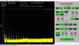
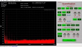
Did you connect a ground reference from the amp to the chassis? While the QA190 has good common mode its not perfect. I am seeing 60 Hz modulations on the left channel. Otherwise its not unusual.
Hello!
Thanks for the reply 1Audio! The powder cord is a 2 prong. The black speaker outputs are connected to chassis ground. Am I clipping an alligator clip from the chassis to somewhere else when I do the distortion measurement? If you could explain the 60 hertz modulation you see in the left channel that would be helpful also. Thanks for giving me the opportunity to learn something here. There is not a lot of support or documentation for this product. Robert
Thanks for the reply 1Audio! The powder cord is a 2 prong. The black speaker outputs are connected to chassis ground. Am I clipping an alligator clip from the chassis to somewhere else when I do the distortion measurement? If you could explain the 60 hertz modulation you see in the left channel that would be helpful also. Thanks for giving me the opportunity to learn something here. There is not a lot of support or documentation for this product. Robert
Just a clip lead from the PC chassis or the QA400 chassis to the amp chassis or ground. Check with a meter first to make sure there isn't a more serious leakage or hot chassis problem.
If you look att the fundamental and harmonics you will see sidebands on each side. I'm guessing they are 60 Hz from the fundamental. Closer inspection will confirm. If they are still there with the extra ground link I would suspect power supply hum. It usually gets worse under load.
If you look att the fundamental and harmonics you will see sidebands on each side. I'm guessing they are 60 Hz from the fundamental. Closer inspection will confirm. If they are still there with the extra ground link I would suspect power supply hum. It usually gets worse under load.
Significant difference between channels -- I'm guessing a bad tube or other circuit problem in the L channel...
Hello!
Thanks for the responses. That really helps. You cannot hear any hum when you play the amp. I know some people modify the power supply on these and add another choke for more filtering. Robert
Thanks for the responses. That really helps. You cannot hear any hum when you play the amp. I know some people modify the power supply on these and add another choke for more filtering. Robert
Increase the "AVG" to 10... it is at zero now.
set the fundamental level to about -10dB.
Btw, 0.02% seems too low for a typical ST-70 tube amp.
What is the actual output level from the amp in either volts or watts? And
are you using a dummy load on the output of the amp?
set the fundamental level to about -10dB.
Btw, 0.02% seems too low for a typical ST-70 tube amp.
What is the actual output level from the amp in either volts or watts? And
are you using a dummy load on the output of the amp?
Hello!
I will change the average from 0 to 10. I see the knob for "average". What will that do? Yes, .02 distortion for a tube amp does not seem correct, which is one of the main reasons for posting. I do notice a wire in the left channel going past the rectifier tube and 2 electrolytic caps. I bet if I reroute the wire, some of that 60 hertz hum will clear up in that channel. I still need to figure out how to take a power measurement with the QA400 and QA190. The instructions are seriously lacking, but the price is great. Thanks for keeping this fun! Robert
I will change the average from 0 to 10. I see the knob for "average". What will that do? Yes, .02 distortion for a tube amp does not seem correct, which is one of the main reasons for posting. I do notice a wire in the left channel going past the rectifier tube and 2 electrolytic caps. I bet if I reroute the wire, some of that 60 hertz hum will clear up in that channel. I still need to figure out how to take a power measurement with the QA400 and QA190. The instructions are seriously lacking, but the price is great. Thanks for keeping this fun! Robert
Do you have a dummy load on the amp?
The increased average will drop the noise out somewhat and give a result that is "better".
Not sure this instrument is going to give you a direct power reading.
Ohm's law is going to tell you the power...
The increased average will drop the noise out somewhat and give a result that is "better".
Not sure this instrument is going to give you a direct power reading.
Ohm's law is going to tell you the power...
I do notice a wire in the left channel going past the rectifier tube and 2 electrolytic caps. I bet if I reroute the wire, some of that 60 hertz hum will clear up in that channel. Robert
At the rectifier and caps you don't have 60 Hz - it's 120 Hz and up at that point.
Jan
Hello!
Yes, I have dummy loads on the output. I think 200 watt 8ohm that I got from Parts Express. They are huge bricks. I will play around with the settings and see where I land. Thanks for taking the time to reply. Robert
Yes, I have dummy loads on the output. I think 200 watt 8ohm that I got from Parts Express. They are huge bricks. I will play around with the settings and see where I land. Thanks for taking the time to reply. Robert
Last edited:
I just got my QA400 today. When calibrating, my AC voltmeter reads 0.8 VAC each channel. This is not acceptable to the calibration routine.
Should I have accepted the defaults? I think they were 1.29
TFM says to check with a scope, it looks ok, so I accepted the defaults.
The loopback test is excellent. Very little difference between channels.
Should I have accepted the defaults? I think they were 1.29
TFM says to check with a scope, it looks ok, so I accepted the defaults.
The loopback test is excellent. Very little difference between channels.
Last edited:
- Home
- Design & Build
- Equipment & Tools
- QuantAsylum QA400 and QA401