Since I don't see a schematic I can't really help you, but you can always parallel them to get more current drive, and I would think 250mA would be plenty to drive 50 ohms at very low distortion.
Hi dirkwright,
I evaluated the LME49600. It pretty good but doesn't quite make it to the level I'm after.
Thanks for the tip though.
Do you remember whether it was 2nd or 3rd that was too high, or both? The non-inverting buffer is a very difficult problem at -120 and below. I'm dealing with those issues on the Boonton. The differential input is fine on the X1 range, but X10 causes a significant increase in 3rd harmonic. My guess is the source impedance of the divider and the input cap modulation of the opamp are causing the problem. In the Shibasoku they went to extremes to cascode jfets as followers into the bipolar input diff pair. I think this is what it will take to make that buffer work below -120 db harmonics. i don't think this will be easy in an opamp. I have sketched out a discrete/opamp combo for this but it felt like an extreme effort. Below and attached. It felt odd to use so many discrete parts with an opamp.
Attachments
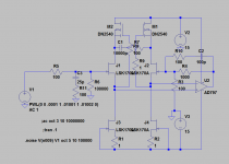
You can use the DN2530 instead of the 2540 if you want a smaller parts package. I thought the problem was driving something on the output of the opamp, not buffering the input. I would replace J3 and J4 with calibrated current limiting diodes, which will save some effort. You also may be pleased to know that Linear Systems has introduced the P channel complement to the LSK170.
http://www.linearsystems.com/products_details.php?pr=jfet-amplifiers--singles&pro_id=69
http://www.linearsystems.com/products_details.php?pr=jfet-amplifiers--singles&pro_id=69
Do you remember whether it was 2nd or 3rd that was too high, or both? The non-inverting buffer is a very difficult problem at -120 and below. I'm dealing with those issues on the Boonton. The differential input is fine on the X1 range, but X10 causes a significant increase in 3rd harmonic. My guess is the source impedance of the divider and the input cap modulation of the opamp are causing the problem. In the Shibasoku they went to extremes to cascode jfets as followers into the bipolar input diff pair. I think this is what it will take to make that buffer work below -120 db harmonics. i don't think this will be easy in an opamp. I have sketched out a discrete/opamp combo for this but it felt like an extreme effort. Below and attached. It felt odd to use so many discrete parts with an opamp.
I tried several op amps. The one that worked best was the LME49990. Without loading the this op amp buffer combo was transparent. it was both 2nd and 3rd but the 2nd was dominate. Nothing above that harmonic order. But I see this every thing I try.
It was about the same inverted mode and common mode..
I measured a strong second harmonic in the low mV's across the rails under loaded conditions. I think this is getting back into the amplifier. My power supply and leads are giving some 0.06 ohm Z. Not good. Maybe better regulation is required.
As per the datasheet for the LME49990, extensive power supply pin bypassing is required. This makes this opamp very difficult to use in practice.
I tried several op amps. The one that worked best was the LME49990. Without loading the this op amp buffer combo was transparent. it was both 2nd and 3rd but the 2nd was dominate. Nothing above that harmonic order. But I see this every thing I try.
It was about the same inverted mode and common mode..
At those levels, 2nd higher than 3rd in bipolar circuits is usually due to magnetic effects, so layout, layout, layout... I can't even imagine somebody attempting to breadboard such a circuit.
It all pointing to magnetic effects. This is to be expected when currents become significant.
No breadboard with the LME49600. It's on FR4
RE the THS6012
I don't like cooling a device using copper pours on each side of the board. This creates a dipole antenna making the problem that much worse. However this is TI's recommendation for cooling this device and what's done on the EVM board which was copied. On to layout number 2.
Demian with the LME49600 I had to go to rail to rail bypassing with a single 0.1u from pos pin of the op amp to ground. This cleaned the grounds up significantly and dropped the distortion a couple of orders of magnitude. I think the demo board decoupling is power pins to ground isn't it?
I still have not received the demo board for the LME49600. The bypassing you describe is straight from Bruce Hofer's playbook. I think the only other time I have heard of the trick was from Scott Wurcer on some very difficult circuit application. If you can get there with the LME49990 and LME49600 combo that would be very accessible and not expensive.
The high bias current of the LME49990 and big input transistors will make for some input modulation issues. You can get an idea of the magnitude of the issue by inserting a 1K resistor in series with the input to the LME49990. The higher impedance allows for the modulation to happen. I was thinking of making a module with the Cascoded FET input, LME49990 and LME49600 as a universal invisible amp module. It would be neat if it fit a dip footprint but the power supply demands probably make that unlikely to be successful
The high bias current of the LME49990 and big input transistors will make for some input modulation issues. You can get an idea of the magnitude of the issue by inserting a 1K resistor in series with the input to the LME49990. The higher impedance allows for the modulation to happen. I was thinking of making a module with the Cascoded FET input, LME49990 and LME49600 as a universal invisible amp module. It would be neat if it fit a dip footprint but the power supply demands probably make that unlikely to be successful
I still have not received the demo board for the LME49600. The bypassing you describe is straight from Bruce Hofer's playbook. I think the only other time I have heard of the trick was from Scott Wurcer on some very difficult circuit application. If you can get there with the LME49990 and LME49600 combo that would be very accessible and not expensive.
The high bias current of the LME49990 and big input transistors will make for some input modulation issues. You can get an idea of the magnitude of the issue by inserting a 1K resistor in series with the input to the LME49990. The higher impedance allows for the modulation to happen. I was thinking of making a module with the Cascoded FET input, LME49990 and LME49600 as a universal invisible amp module. It would be neat if it fit a dip footprint but the power supply demands probably make that unlikely to be successful
Well maybe an SIP rather than dip. Fit it in a small grounded aluminum enclosure.
Scott pointed out an old app note of his that illustrates the bypassing in the BT thread.
Can't remember the part number.
Bridging two buffers will keep the load current off the ground.
Hi David,
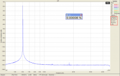
I have finally found the right thread. I am posting the best result that was measured at a colleague of mine, who has better equipment. This one is without a notch filter. We may discuss more in e-mails, regarding higher power output stage, as I wrote you in reply to your PM.
Regards,
Pavel
I have finally found the right thread. I am posting the best result that was measured at a colleague of mine, who has better equipment. This one is without a notch filter. We may discuss more in e-mails, regarding higher power output stage, as I wrote you in reply to your PM.
Regards,
Pavel
Attachments
Hi David,
I have finally found the right thread. I am posting the best result that was measured at a colleague of mine, who has better equipment. This one is without a notch filter. We may discuss more in e-mails, regarding higher power output stage, as I wrote you in reply to your PM.
Regards,
Pavel
10K load?
THx-RNMarsh
The decoupling method mentioned in post #4068 was a good reminder, since I hope to start my design of a similar output stage for my ADC/DAC design soon.
An even better method is probably the method described by e.g. Douglas Self in his book "Audio Power Amplifier Design". In the sixth edition it is in chapter 11. He calls it "Distortion Five", Rail Decoupling Distortion" and "Distortion Six", "Induction Distortion". He is using two capacitors, but the center point is taken back to a star point close to the reservoir capacitors in the power supply.
When driving low impedances from the LME49600 I think it makes sense to use techniques from power amplifier design.
The decoupling method mentioned in post #4068 was a good reminder, since I hope to start my design of a similar output stage for my ADC/DAC design soon.
An even better method is probably the method described by e.g. Douglas Self in his book "Audio Power Amplifier Design". In the sixth edition it is in chapter 11. He calls it "Distortion Five", Rail Decoupling Distortion" and "Distortion Six", "Induction Distortion". He is using two capacitors, but the center point is taken back to a star point close to the reservoir capacitors in the power supply.
When driving low impedances from the LME49600 I think it makes sense to use techniques from power amplifier design.
I have Self's book but it is an early edition. Picked it up many years ago when the internet got going. I should up grade to a recent edition.
Keeping the grounds clean from bypassing is essential but it's also the easy part.
Dealing with the load currents and EM effects is separate challenge.
This part of Douglas' text has been there for a while. I would expect it to be in all editions. At least it is there in the third edition as well.
I agree that keeping things separate and avoid also magnetic coupling is a challenge when doing the layout.
I agree that keeping things separate and avoid also magnetic coupling is a challenge when doing the layout.
Always recommend Henry Ott for ground issues.
looks like he has a newer and expanded edition out as well, now up to 827 pages
EMC Books
this one has also been recommended to me, haven't finished slogging thru it yet, but seems good.
http://www.amazon.com/Digital-Design-Interference-Specifications-Edition/dp/075067282X
Alan
looks like he has a newer and expanded edition out as well, now up to 827 pages
EMC Books
this one has also been recommended to me, haven't finished slogging thru it yet, but seems good.
http://www.amazon.com/Digital-Design-Interference-Specifications-Edition/dp/075067282X
Alan
Last edited:
Hi David,
I have finally found the right thread. I am posting the best result that was measured at a colleague of mine, who has better equipment. This one is without a notch filter. We may discuss more in e-mails, regarding higher power output stage, as I wrote you in reply to your PM.
Regards,
Pavel
Thanks Pavel.
I sent you an email.
Disregard the last PM.
Cheers,
Always recommend Henry Ott for ground issues.
looks like he has a newer and expanded edition out as well, now up to 827 pages
EMC Books
this one has also been recommended to me, haven't finished slogging thru it yet, but seems good.
Digital Design for Interference Specifications, Second Edition: A Practical Handbook for EMI Suppression: David Terrell, R. Kenneth Keenan: 9780750672825: Amazon.com: Books
Alan
I been through Henry's web pages. I used a lot of his suggestion for grounding mixed signal in the oscillator which worked out very well.
Thanks.
Yes, Ott is always good to learn from. I still have the first edition of his "Noise Reduction Techniques in Electronic Systems", which was used as a text book during my engineering studies many years ago.
Do you remember whether it was 2nd or 3rd that was too high, or both? The non-inverting buffer is a very difficult problem at -120 and below. I'm dealing with those issues on the Boonton. The differential input is fine on the X1 range, but X10 causes a significant increase in 3rd harmonic. My guess is the source impedance of the divider and the input cap modulation of the opamp are causing the problem. In the Shibasoku they went to extremes to cascode jfets as followers into the bipolar input diff pair. I think this is what it will take to make that buffer work below -120 db harmonics. i don't think this will be easy in an opamp. I have sketched out a discrete/opamp combo for this but it felt like an extreme effort. Below and attached. It felt odd to use so many discrete parts with an opamp.
I get a rise in both 2nd and 3rd H inserting a 3k resistor in series with the non inverting input. However driven from 100 ohms with buffer at minimum load > 15k ohm the LME49600 in loop with an opa1611 is quite transparent. I get a rise in 2nd to 5th with a 200 ohm load.
This improved some by adding RC rail filtering to the op amp with 100 ohm on each rail and a 100uF cap rail to rail. The 0.1uF from pos rail to ground remaining. Both outputs of the osc are decoupled with a 100 ohm resistor internally.
- Home
- Design & Build
- Equipment & Tools
- Low-distortion Audio-range Oscillator