Thanks !
For the CM I'll try the one from Juma that I adapted for my needs. Thanks for the advice for the CM.
BR,
Eric
For the CM I'll try the one from Juma that I adapted for my needs. Thanks for the advice for the CM.
BR,
Eric
Attachments
Last edited:
Good Idea.
If you can please test it with regular PS one side and with the the other side so make sure these will be an improvement.
Very likely do but if you can please test it.
Greetings
If you can please test it with regular PS one side and with the the other side so make sure these will be an improvement.
Very likely do but if you can please test it.
Greetings
When using a cap multiplier ignore Elliots advice about placing the big cap first - place the big cap at the output and this will dominate the overall sound of the power supply rather than the cap multiplier. This is Nelson Passes advice.
Shoog
Shoog
Thanks for the hint Shoog.
For my current prototype, when powered at +/- 14Vdc with a bias of 1.25A my Output power is 8W@8ohm and 10W@4ohm just before clipping. This is what I was aiming for but I was under the impression that the power would of double into the 4 ohm load...
My output voltage across the 8 ohm load is 8Vrms (before clipping) and goes down to 6Vrms when the load is 4ohm...
Signal is 1KHz sine wave.
Any explanation..
p.s. Great sound by the way.
TIA,
Eric
For my current prototype, when powered at +/- 14Vdc with a bias of 1.25A my Output power is 8W@8ohm and 10W@4ohm just before clipping. This is what I was aiming for but I was under the impression that the power would of double into the 4 ohm load...
My output voltage across the 8 ohm load is 8Vrms (before clipping) and goes down to 6Vrms when the load is 4ohm...

Signal is 1KHz sine wave.
Any explanation..
p.s. Great sound by the way.
TIA,
Eric
Last edited:
Could someone confirm the following to see if I understand.
I measured 10W@4ohm and 8W@8ohm;
Available output bias is 1.25A which gives me 8W@8ohm, since the bias remains constant I will have 1/2 the output power at 1/2 the load so 4W @ 4 ohm of Class A and the remaining 6W @ 4ohm is Class AB.
I think this makes sense, doesn't it ?
Thanks,
Eric
I measured 10W@4ohm and 8W@8ohm;
Available output bias is 1.25A which gives me 8W@8ohm, since the bias remains constant I will have 1/2 the output power at 1/2 the load so 4W @ 4 ohm of Class A and the remaining 6W @ 4ohm is Class AB.
I think this makes sense, doesn't it ?
Thanks,
Eric
See this thread post 761 and 764, Lineup also had an increase in output power but had to increase his bias from 1A (for 8 ohm load) to 1.5A (for 4 ohm load), this was with a +/- 16Vdc supply.
I think I will leave mine as is, the sound is good and that's all that matters ;-)
I think I will leave mine as is, the sound is good and that's all that matters ;-)
It shouldn't make a difference as simulations show that it will transition into Class AB when the original bias is exceeded. My simulation showed it delivering over 1amp when the output hit the rails with a bias setting of 800mA.
This is how any amplifier should work, the bias setting is not a limit to output current, just a limit to how much current is delivered before it leaves Class A.
Shoog
This is how any amplifier should work, the bias setting is not a limit to output current, just a limit to how much current is delivered before it leaves Class A.
Shoog
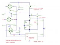
Regulated supply for LeMonstre
My supply is based on a simple adaptation of Hiraga's regulated power supply.
However, due to the low voltages, the original circuit does not work well enough.
I had to add a voltage doubler as an extra input to make the regulation work. It is very effective now. The negative rail is the same, just mirrored.

I made small circuit boards for each regulator. Locally there is need for a small Zobel. I used 5,6 uF solid tantal. Otherwise it oscillates in the megahertz region.
The large capacitor where the amplifier units are connected to can be 10.000uF, I switched to 2.500uF at the end. Having such a reservoir is necessary to be able to pass dynamics I suppose. I did not do a test with and without them, have not had time yet.
I decided on a bias of 0,7 A, after warming up this rises to about 0,8 A.
My supply is based on a simple adaptation of Hiraga's regulated power supply.
However, due to the low voltages, the original circuit does not work well enough.
I had to add a voltage doubler as an extra input to make the regulation work. It is very effective now. The negative rail is the same, just mirrored.

I made small circuit boards for each regulator. Locally there is need for a small Zobel. I used 5,6 uF solid tantal. Otherwise it oscillates in the megahertz region.
The large capacitor where the amplifier units are connected to can be 10.000uF, I switched to 2.500uF at the end. Having such a reservoir is necessary to be able to pass dynamics I suppose. I did not do a test with and without them, have not had time yet.
I decided on a bias of 0,7 A, after warming up this rises to about 0,8 A.
"Le Monstre" vs. Le Class A"
Both front-end and output stage (CFP/Sziklai darlington) are different - go to
The Class-A Amplifier Site - Hiraga 20W Class-A
and
Jean Hiraga's Le Monstre / Monster - DIY Class-A 8W Amplifier
In the schematic of first URL you will find resistors in the collector leads of first stage from the CFP. This resistors I miss in the schema of second URL.
What are the pros and cons, if I use resistors at this place?
I guess, the absence of this resistors provides the effect, that the current flow in the first stage of CFP is dependend of the currently idle current flow in the second stage of the CFP. Is my estimate right?
Hi,
the "Le Monstre" was a pure DIY project in that "L'Audiophile" magazin, whereas its big brother, the "Hiraga Le Classe A" was also a commercial realisation.
I try to load a pic of a commercial "Classe A", which was the first realisation of that amp, with 20W power each channel. The later revised "Le Classe A" had up to 30W per channel, and bigger lytics in the filter stage 330 000 uF (4 times).
BTW, later years of production are much prettier.
regards,
Hartmut
Both front-end and output stage (CFP/Sziklai darlington) are different - go to
The Class-A Amplifier Site - Hiraga 20W Class-A
and
Jean Hiraga's Le Monstre / Monster - DIY Class-A 8W Amplifier
In the schematic of first URL you will find resistors in the collector leads of first stage from the CFP. This resistors I miss in the schema of second URL.
What are the pros and cons, if I use resistors at this place?
I guess, the absence of this resistors provides the effect, that the current flow in the first stage of CFP is dependend of the currently idle current flow in the second stage of the CFP. Is my estimate right?
Yes, the combination of the LeMonstre Darlingnot is that ALL current in class A of the driver transistor 2SB716 goes through the output transistor. There must be a good match of transistors in Hfe. Looking at the top side: the driver must not be pinched off in a negative input signal when nearly all current is cut off in the output - but not yet in the driver. So matching of the pair is tricky in the design. In the later LeClasse A the collector resistor 1K8 keeps the driver in conduction always for sure.
 Someone who has a simulation model can support or reject my observations.
Help with non-functioning board
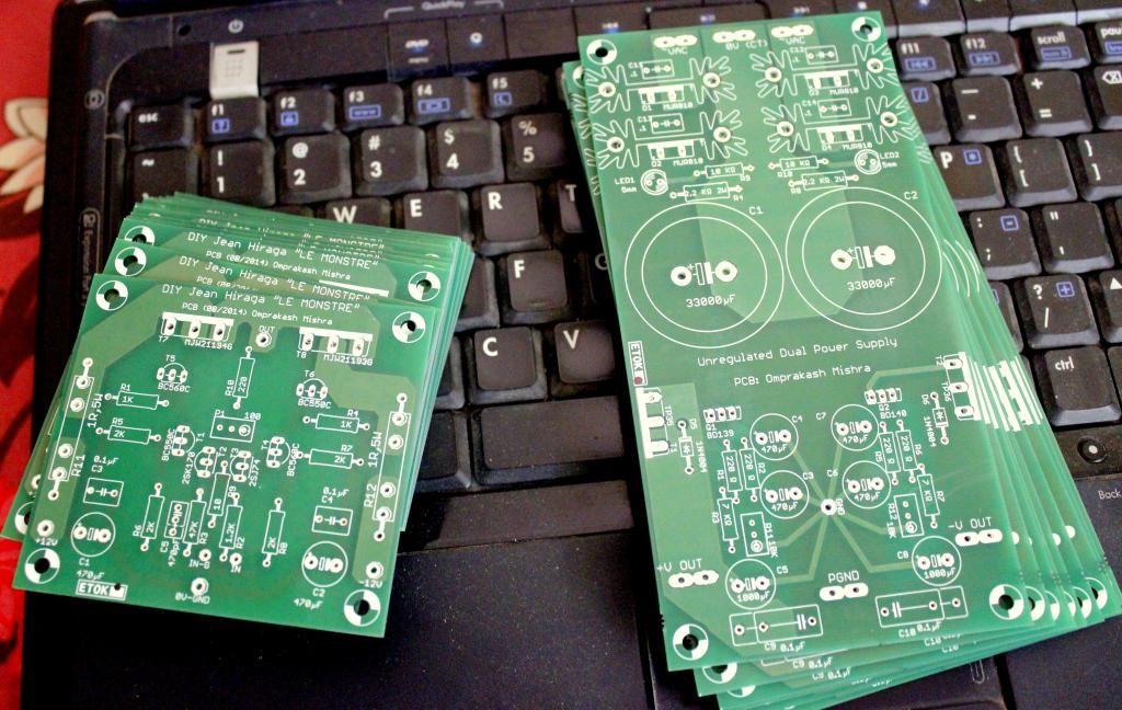
I built two Hiraga Monstre boards from ebay (see attached images), one channel is working fine, but I would need advice as the second board is not working and I do not know how to fix it.
The board only produces hum in the speaker, the voltage across the 1 Ohm power resistor (R11 and R12 are replaced by a 1 Ohm resistor) is too high at 1.25 V (that is the bias current is 1250 mA instead of the 800 mA on the other channel). The offset at the speaker terminals can be correctly adjusted with the potentiometer to 0V. Curiously when the power is unplugged and the rail voltage drops from +/-13.4 V for some time while the buffer capacitor has lower voltage music can be heard in the speaker. I checked for bad solder spots and correct part placement. What problem could there be / which parts could I swap from the working board to see whether a transistor is blown? Any other ideas?
Thanks in advance for your help!
Attachments
This can happen if your darlington transistors are faulty. Perform a diode test with a multimeter on each transistor comparing one channel to the other.
Shoog
Shoog
Thanks a lot for the tip -all the readings for the darlington transistors with the multimeter diode tester are the same. Would you suggest nevertheless to swap the transistors in the two Darlington pairs one by one? Or could I test something else before?
I am a bit puzzled that as soon as it is driven from the buffer capacitors only music plays all right, but with the full 13.4V power rails there is very lood hum overshadowing the music. At first I thought the signal cable would pick up noise from the power supply but this would not explain the bias current that is to high at 1.3 A through the two output transistors.
Thanks in advance for any further tips what to try.
I assume outputs are not busted.
then:
What you can do is test the voltages on R2 and R3. They should be about the same (within 10 mV or so).
You can change the R2 and R3 with a potmeter for testing. Slowly turn up from about 500 ohms to a value where current starts to run.
You don't have to do it life (with voltage), you can also do it in steps.
[tip based on the Pass F5 instruction manual].
Why?
The root cause might be that the FETS have an unequal Idss.

Thank you very much for this tip (this forum is great!) 🙂
I reduced the value of R2 and R3 by putting 1k R in R4 and R5 positions (the ebay seller came back to me with the same tip to adjust R2 and R3) and the bias current reduced by more than a factor of two to 540 mA 🙂
Would you suggest to adjust the resistor value for the proper 700 mA bias current and then live with it?
Or would the proper way be to get a new pair Q3 Q7 of 2SK170BL and 2SJ74BL?
It is to me of no problem to have a higher Idss value and a lower R2 R3, but I may remind that Hiraga preferred the lower Idss version of 2SK170BL and 2SJ74BL.
I like to think about it as follows: The amplification with a lower R2R3 is also lower (relationship of R2 R3 and the 10 ohm source resistor). But I'm not sure the math works like that.
And a lower Idss of 2SK170BL and 2SJ74BL is hard to find.
So my suggestion: stick to it and adjust to 700 mA - that works great.
- Home
- Amplifiers
- Solid State
- Hiraga "Le Monstre"


