off-course it plays... don't think that the poweramp is the right place to compensate for warped records...🙂 we still need to crack the mono-mixing below 50hz
It's the cap connecting the feed back network to GND I am referring to, increase that end get a lower cut off frequency an less LF phase shift
Thank you Miib, in that place I have a 680uF BGN (nonpolar).... for now I am quite pleased with the result but I will experiment doubling it 🙂
off-course it plays... don't think that the poweramp is the right place to compensate for warped records...🙂 we still need to crack the mono-mixing below 50hz
Yes, I new it would play the first time you posted your schematic review 🙂
Mono mixing below 50Hz... please elaborate....
I do not have any issues with warped records and my riaa preamps all have a built in low freq rolloff (all but the paradise)
you can have a DC coupled phono-stage without getting the flobbing from the speaker drivers if you mange to mix the lowest frequencies into mono.
That would be a major complexity in the riaa amp 🙂
I always found that a fine cart/arm/TT combination eliminates that issue.
I always found that a fine cart/arm/TT combination eliminates that issue.
Now connected to my main system I confirm my initial impressions.
Bass is present but not overwhelming while retaining a very good detail. I like that because bass "contrabaixo" is one of my preferred instruments as it was one I used to play in the old days 🙂.... NHOP sounds really good in the several pieces I listened to.
Mids are well integrated and convey a credible presentation to the whole.
Highs are good but do seem to lack that "ultimate" spatiality I am used from the Meridian or Quad amps I use normally.
Stage width is quite good and the amp is quite "musical" in the sence that makes us forget about it and really listen to the music.
As for reality, it lacks the "finesse" of the Meridian particularly with piano and some wind instruments that tend to be slightly "hard".
I believe this is the typical signature of SM caps that I used for miller so I plan to replace those with something less hard but as detailed as.... I particularly like the copper foil on polystyrene from relcap..... Now I have one important question... I have two 30pF caps of this type, can I replace the 47pf miller for those 30pf without impairing the amp stability ?
Hi
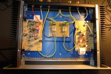
I suspect the area of your fuse board, with its long, wandering leads is going to cause problems in the amplifier since they carry the power supply and all its switching pulse energy is free to radiate to the feedback and input sections. That increases HF distortion.
Consider reducing that loop area of the supply by shrinking the fuse board drastically and mounting it right at the power connector. Then twist the supply lead pairs to the boards to cancel radiated EM fields and reduce their overall length to a minimum.
Last edited:
Hi Ian
Thank you for your comments. The psu lines are indeed a mess.... I just did it this way because I used the case from a previous amp and wanted to use the old connections.
Thank you for your comments. The psu lines are indeed a mess.... I just did it this way because I used the case from a previous amp and wanted to use the old connections.
After some more listening sessions I believe the treble should be improved. It is somehow "splashy".
I believe I am experiencing the effects of too low slew rate.
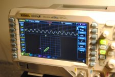
Input transistor collector current presents compression when I input 1v at high frequencies square wave.
Reducing the miller cap to 20p seems to improve matters a lot (in simulation)
Can I replace the 47p cap without fear of oscilations ?
The BD140 used for VAS has a rather high Cob.... maybe it can cope with a smaller miller cap.
I believe I am experiencing the effects of too low slew rate.
Input transistor collector current presents compression when I input 1v at high frequencies square wave.
Reducing the miller cap to 20p seems to improve matters a lot (in simulation)
Can I replace the 47p cap without fear of oscilations ?
The BD140 used for VAS has a rather high Cob.... maybe it can cope with a smaller miller cap.
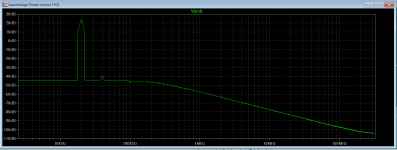
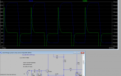
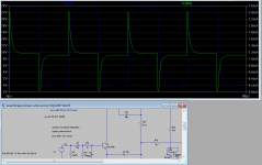
See what happens at the current on the collector of the input transistor when we input a 1v square wave.
One pic with 47p for miller, the other with 10p in the same location....
Can I reduce the miller cap without needing to increase gain ? (I would like to keep NFB as is)
One pic with 47p for miller, the other with 10p in the same location....
Can I reduce the miller cap without needing to increase gain ? (I would like to keep NFB as is)
Attachments
See what happens at the current on the collector of the input transistor when we input a 1v square wave.
One pic with 47p for miller, the other with 10p in the same location....
Can I reduce the miller cap without needing to increase gain ? (I would like to keep NFB as is)
When using 22p the simulation shows 22dB/66deg. 10p gives 21dB/64deg, still usable. That should be enough.
Last edited:
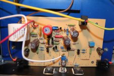
There are things that can be done to improve the design, the VAS needs to be strong and run hot, the mirrors for the bias spreaders can be made higher in impedance. stacking two mirrors and using beta enhancement comes to mind.
Maybe cap voltage stabilization around the two 1K ohm resistors over the VBE.
When I look at designs I normally try to make currents as high-impedance as possible and voltage as low in impedance as possible.
Maybe cap voltage stabilization around the two 1K ohm resistors over the VBE.
When I look at designs I normally try to make currents as high-impedance as possible and voltage as low in impedance as possible.
Last edited:
Hi Miib
I am open to any suggestions that might improve sound quality.
As for the VAS, should I increase it's collector current ?
The mirrors can be improved how... like the mirrors in the paradise ?
I am open to any suggestions that might improve sound quality.
As for the VAS, should I increase it's collector current ?
The mirrors can be improved how... like the mirrors in the paradise ?
I am afraid this higher current might create a higher variation of offset due to temp changes as it seems much more sensible to adjustements in the offset pot (now set to 17.14k)
Such a simple design will always have it´s technical limits but can sound very good.
I would replace the VAS transistor by a Sanyo Video Driver.
I would replace the VAS transistor by a Sanyo Video Driver.
- Home
- Amplifiers
- Solid State
- Assemblage Power Amp