Yes, 60° is often recommended because it is a good compromise between stability and bandwidth. You can make the amp more stable by making it slower.
I think Ricardos numbers are fine.
I think Ricardos numbers are fine.
Yes, 60° is often recommended because it is a good compromise between stability and bandwidth. You can make the amp more stable by making it slower.
I think Ricardos numbers are fine.
Yes that is what I said here
Here the GBW, Gain Margin and Phase Margin plots and figures for the Exicon amplifier version (a Tian-Probe was used). The amplifier should be stable ( 25gm > 20minimum, 74pm > 60minimum).
But where did I get the 20/60 numbers, or am I just making things up? Mmm... do I need to get my head examinationed?
While stability is mostly in a global frame, good practice must be looked at as things can happen locally as well. Trace inductance paired with cob can cause local problems, this is the reason for the local cap at the MOSFET drain
Perfect
So I just need a small cap on the drain, maybe even a small film...
And If everything is ok I can build it without the 10pF from gate to drain... (You stated 22p but you left 10p on the schematic)
So I just need a small cap on the drain, maybe even a small film...
And If everything is ok I can build it without the 10pF from gate to drain... (You stated 22p but you left 10p on the schematic)
Just finished one board.... It works... it amplifies with 27dB gain at 1khz... No nasties on the scope.
Tempco is negative at +-180mA idle. (on positive and negative sides)
I am testing it without load.
It is possible to zero output offset just by trimming R24.
Now the first (possible) issue:
ECX10N gate sits at the previsible +650mV but ECX10P gate sits at -1.3V
I was expecting a symmetry here and the negative side should have the gate at -650mV... does it indicate a major issue ?
There will always be a little difference in the DGS voltages of the Lat-Fets. When you get the offsets trimmed it will be less. The ofset can be trimmed by a parallel trimmer to one of the emitter-resistors in the biasing current mirror. for future projects like this thers also the option of tiring a four transistor CCS to a central GND point and then trim the up and down currents in the biasing current mirror. and easier way to make the floating CCS is to use a depletion mosfet like the supertex
In this case, what mirror should I look into ?
The mirror in the positive side does produce more current than the one in the negative side (0.5mA more)
The mirror in the positive side does produce more current than the one in the negative side (0.5mA more)
Measure your offset, then use spice to generate the opposite offset, by adjusting the mirror resistor, then you should be good to go, I suspect that a 1-5 Kohm esistor parallel over one mirror resistor will null the offset
After some simulation and some resistor trimming I finally got almost symmetrical gate values and source currents.
Now I will start building second channel 🙂
Now I will start building second channel 🙂
Just finished second board and although I took the trouble to match all the transistors and resistors this time, the results are identical to the previous board.
I have -1.2v and +0.7v in the mosfets gates.... If I trim the resistors values in the mirrors I can really minimize the difference but I forgot to trim the offset.... after I zero offset in the vbe multiplier at the input, I get always a difference in the gates of the mosfets.
The current in both rails is the same so I guess it is ok to leave it as is.
Now I will place the boards on a case and will soon be posting subjective listening impressions 🙂
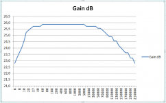
Gain is quite high at 26dB
It goes from 6Hz to 210kHz at -3dB.
It does have Low freq phase shift under 100Hz....
It goes from 6Hz to 210kHz at -3dB.
It does have Low freq phase shift under 100Hz....
Just finished second board and although I took the trouble to match all the transistors and resistors this time, the results are identical to the previous board.
🙂
Gain is quite high at 26dB
You can increase the feedback a bit, this will yield lower closed loop gain and maybe even better (at the least measured) performance. The point is, if you have to much gain, do not destroy it using a volume control, but use it to improve performance (if possible).
C1 bypassing the bias vbe multiplier is already 47uF.if you want better LF response increase C-1 to a larger size. evt like 2,2mF
Anyway today I finished the enclosure and after trimming the offset I pluged into my lab system and guess what.... Incredibly musical, powerfull bass, dynamic and not harsh in any respect. This is a serious amp. What I am really appreciating is the detail it is able to retrieve from the sources.
Can not seriously comment because my lab system uses Yamaha 1000 monitors and a pedja buffer as volume control but it seems quite promising.
During next week I will plug it into my main system so I can really evaluate it.
It's the cap connecting the feed back network to GND I am referring to, increase that end get a lower cut off frequency an less LF phase shift
IT PLAYES !
A testimonial from theory to praxis in one go.
Super extended bass can be a problem with vinyl.
A testimonial from theory to praxis in one go.
Super extended bass can be a problem with vinyl.
- Home
- Amplifiers
- Solid State
- Assemblage Power Amp