Yes Andrew, the engineering answer is as you have described altho sometimes the extra local decoupling caps can produce problems of their own, unfortunately - nothing's ever simple!
Particularly with headamps, sometimes changing components on the mains side of the transformer can have quite noticeable effects on the sound but never seem to show up on the CRO or meters
Typical ones like dc traps to get rid of transformer partial saturation, tuning caps that still puzzle people how they work, different power cords, EI/R-Core/Torroid transformers, etc, etc, diode switching and snubbers that are pretty well sorted, power filter components, and so on - plenty of fertile ground for nattering on!
Very little of it can be designed on paper/tested/optomised by theory but the 'sound effects' are quite apparent and is still quite annoying to my engineering background but, over the years I've become more accepting of things I don't understand - there's plenty of that!
I'm quite surprised that the more recent version of Salas's ReflectorD regulator apparently produces significantly better results than the previous ones, as per Merlin's one too - can't figure that one out, but ....
you can't overdamp the snubber.What happens (subjectively speaking) if overdamping the snubber?
The resistance becomes too low to absorb the pulse energy and the secondary starts ringing again when r < Roptimum.
the ability to replay dynamics is totally dependant on current supply.
That current comes from the local decoupling and the last smoothing capacitor stage.
The current to the load does NOT come from the transformer, thus the current supply is NOT affected by the snubber used on the transformer secondary.
BUT
ringing of the supply will affect the amplifier and this can leak to the load. This can sometimes be audible. Some listeners hear the "extra detail" of the HF components of the ringing and declare "much better".
Ears tells lies, sometimes !
you can't overdamp the snubber.
The resistance becomes too low to absorb the pulse energy and the secondary starts ringing again when r < Roptimum.
With 47R happened exactly you said "extra detail" HF with weak lows and mids so I assume the TX is ringing, why the scope don't show the tx ringing?
you can't overdamp the snubber.
The resistance becomes too low to absorb the pulse energy and the secondary starts ringing again when r < Roptimum.
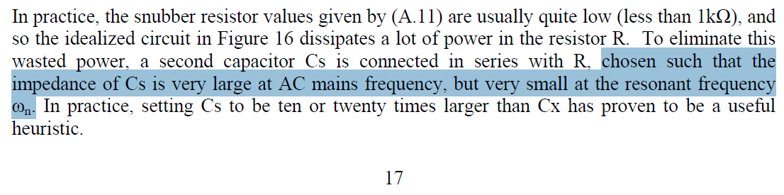
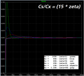
Actually it's possible to overdamp the transformer as much as you wish ... BUT, as you increase the damping factor zeta (by decreasing the damping resistor Rs), you must also increase the power saving capacitor Cs by the same factor.
The Quasimodo design note briefly mentions the Cs requirement (@ zeta=1), in appendix A:
Vary Rs while keeping Cs constant (@ 150nF); you'll get a plot that looks like this:
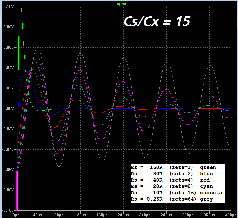

Mathematically inclined readers will, at this point, be screaming at their computer screens: OF COURSE!! The second order differential equation does not lie: wildly overdamped (zeta>60) solutions do exist, just as DiffEq textbooks have said for the past 100 years. To see this with greatest clarity, remove the stupid power-saving kludge (Cs); replace it by a short circuit. Voila, any damping factor zeta>>1 you wish, with no ringing whatsoever. Now reinsert Cs but do not forget that its job is to approximate a short circuit, and don't be a blockhead.
_
Attachments

Last edited:

I guess for HV secondary tx have I to use the caps rated like the HV secondary, right?
Last edited:
With 47R happened exactly you said "extra detail" HF with weak lows and mids so I assume the TX is ringing, why the scope don't show the tx ringing?
As I see on other pics must be my old scope can't have enough resolution?
Last edited:
Mark,
I can't follow your explanation.
With some capacitance across the secondary and the inherent inductance of the secondary, we have a system that can ring/oscilate if a pulse is applied.
Add an optimal resistance in series with the added capacitance and we have an optimally damped pulse and "controlled" overshoot.
make the resistor bigger and the ringing gets worse.
or
make the resistor smaller and the ringing gets worse.
Make the resistor infinitely big and its as if the extra capacitor was switched out, equals bad ringing.
Make the resistor infinitely small and it's as if the extra capacitor is added to the original capacitance, equals bad ringing at a lower frequency.
Only a small range of resistance around the optimal value controls the overshoot so that ringing does not happen.
Too small a resistance is not the same as very high Zeta, if the ringing gets worse.
This is where you lost me.
If we make the resistor significantly smaller than the optimal value, what has high zeta got to do with the system?
Last edited:
For us living on the other side of Atlantic...
Would it make a measurable difference on the optimal Rs to tune the 555 timer to 100Hz?
Would it make a measurable difference on the optimal Rs to tune the 555 timer to 100Hz?
Mark, I can't follow your explanation.
I recommend you perform these three experiments on a real transformer with your CheapoModo / Quasimodo.
- Using Cx = 0.01uF, Cs = 0.15uF, find the value of Rsnub which gives the zeta=1.00 snubbed waveshape shown in post #143 (Dec 2013). Write down (Zeta = 1 at Rsnub = _your_resistor_value_)
- Remove Cs and replace it with a 3.3uF film capacitor such as the one shown in the attachment below. Using Cx = 0.01uF, and Rsnub = (the resistor value in step 1), verify that you get the same zeta=1.00 waveshape as in step 1. Now remove the Rsnub trimmer from its socket, connect it to your ohmmeter, and dial the trimmer to get (0.2 x the resistor value in step 1). You are reducing the value of Rsnub by a factor of 5. Put the trimmer back in the CheapoModo socket and look at the waveform with this new Rsnub. Cowabunga! No ringing. Your CheapoModo is running at zeta=5 and there is no ringing. {You are operating at Cs/Cx = 3.3/0.01 = 330}
- Remove Cs and replace it with a jumper wire; a short circuit. Again verity that with Rsnub = (the resistor value in step 1), you get the same zeta=1.00 waveshape as in step 1. Now dial down the Rsnub trimmer to 1/50th of the resistance value as in step 1. Look at the waveform with this new Rsnub. Cowabunga! No ringing. Your CheapoModo is running at zeta=50 and there is no ringing.
Attachments
Last edited:
No.Would it make a measurable difference on the optimal Rs to tune the 555 timer to 100Hz?
100 Hz gives a 5 msec high time and a 5 msec low time. 120 Hz gives a 4.1 msec high time and a 4.1 msec low time. But (Quasimodo + your transformer) produces waveforms that damp out and go dead, flat-line, no-coronary-activity-whatsoever, after less than 1 millisecond. 120 Hz makes the transformer wait another 3.1 msec after all goes dead, before resetting. 100 Hz makes the transformer wait another 4 msec after all goes dead, before resetting. Either one is perfectly acceptable.
Look at some typical waveshapes from Quasimodo measurements such as (these in post #143). All of the activity is completely damped out and He-is-dead-Jim flatline, after 200 microseconds or so. If you look very closely at the Quasimodo design note, you can find an example that needs an entire millisecond to die out (hint: see page 10). But that's all it needs.
Perhaps you refer to the Frequency Select dipswitch which is present in QM v.4 but absent from QM v.3. Have some fun with your calculator and the LMC555 datasheet: figure out what frequencies the oscillator runs, when various switches are open or closed. (Hint: none of them are 100 Hz)
I did my own experiment with two transformers and el cheapo.
A cap + variable resistor.
vary the resistor from max to min and the ringing goes from max to min to max.
Roptimum is the vR resistance when ringing is minimum.
A cap + variable resistor.
vary the resistor from max to min and the ringing goes from max to min to max.
Roptimum is the vR resistance when ringing is minimum.
SMPS are riddled with snubbers.
If the snubbers are not incorporated, the smps will not work properly.
Open up a competently designed and built smps and count the snubbers.
I seem to remember seeing more than a dozen inside a PC smps.
Since the snubbers are already fitted one does not need to add any more snubbers to the transformer inside the SMPS.
- Home
- Amplifiers
- Power Supplies
- Simple, no-math transformer snubber using Quasimodo test-jig