Mark,
thats a lovely circuit. i like it, and will have a tech build me one so i can give it to the engineers at work who are allergic to analysis.
thats a lovely circuit. i like it, and will have a tech build me one so i can give it to the engineers at work who are allergic to analysis.
Using 15VDC to supply Quasimodo, attached infinityR
Attachments
![WP_20140911_001[1].jpg](/community/data/attachments/388/388607-6b99231ccb12920dc824db1e5d4fe6d6.jpg?hash=a5kjHMsSkg)
Last edited:
![WP_20140911_002[1].jpg](/community/data/attachments/388/388626-3528c85d71bb6bc7f7cde99efdfb4cda.jpg?hash=NSjIXXG7a8)
![WP_20140911_003[1].jpg](/community/data/attachments/388/388643-283c0cdb9d006b5cd7919b7cd4ccf3de.jpg?hash=KDwM250Aa1)
![WP_20140911_005[1].jpg](/community/data/attachments/388/388655-fdbf1c80929039a29da3ebd0abf69237.jpg?hash=_b8cgJKQOa)
![WP_20140911_006[1].jpg](/community/data/attachments/388/388674-1fc64737c5ed6f0de8d808a8d0c04086.jpg?hash=H8ZHN8Xtbw)
Merlin, any chance of doing a comparison oscilloscope snapshot of say 250ohm snubber again, but this time with a 50 ohm loading on primary winding (rather than short circuit) ?
Ciao, Tim
Ciao, Tim
![WP_20140911_007[1].jpg](/community/data/attachments/388/388769-a136f0f379474fafb6c1e8406a00e7f4.jpg?hash=oTbw83lHT6)
Mark when Quasimodo operates the LED is intermittent (shine & not shine) but when operates certain time the LED don't shine?
Last edited:
... when Quasimodo operates the LED is intermittent shine & not shine but when operates certain time the LED don't shine ...
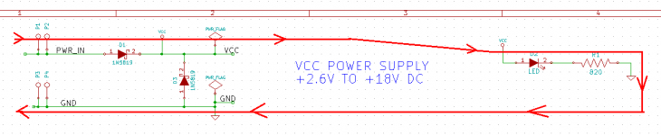
Your Quasimodo v.4 is broken. Here is the relevant portion of its schematic; D2 is the LED. D1 and D3 are protection diodes which prevent overcurrent if someone connects the power supply backwards.
As you can see, there is a pure DC current path (red arrows) from PWR_IN to GND which flows through the LED. The path is
- P1 (external I/O pin) receives PWR_IN from power supply
- D1 Anode
- D1 Cathode (node name: VCC)
- LED Anode (node name: VCC)
- LED Cathode
- 820 ohm resistor R1
- GND
- P3 (external I/O pin) receives GND from power supply
Attachments
Have you read the datasheet? Carefully search for the word near the green and black arrowhead . . . . .

_
_
Attachments
Last edited:
- Home
- Amplifiers
- Power Supplies
- Simple, no-math transformer snubber using Quasimodo test-jig