3) He changed the JFET to 2SK246/J103 and the 1K resistors to 390R. IS the 1K changed because of the JFET change?
4) I have both the 2SK246/J103 and the 2SK170/J74 ordered. Is there a preference on these?
Some findings regarding the JFETs used in "Le Monstre":
The original design uses the JFETs 2SK170Y/2SJ74Y which yield a current of approximately 1.3 mA in the input stage. The voltage drop across the 1 kOhm resistor is 1.3 V and the quiescent current in the output stage becomes 0.6 A. That's the original design and it is simply the best because it provides a substantial voltage gain of 7 in the input stage. Unfortunately these JFETs with IDSS classification Y are almost impossible to get nowadays.
The JFETs 2SK170GR/2SJ74GR yield a current of approximately 2.5 mA in the input stage. In order to maintain the quiescent current of 0.6 A you have to reduce the 1 kOhm resistor to about 520 Ohm. The voltage gain in the input stage drops to 4 (-5 dB).
The new version using the JFETs 2SK246GR/2SJ103GR and a 470 Ohm trim-pot yields a current of approximately 2.7 mA in the input stage. For a quiescent current of 0.6 A a load resistor around 480 Ohm is appropriate. But there's a big problem with these JFETs. The forward transfer admittance is significantly lower and the voltage gain in the input stage only is 1 (-17 dB). Hence the new version clearly is inferior, a loss of 17 dB in open loop gain is way too much IMO.
Conclusion: Go for the original JFETs with the lowest IDSS you can find. They are unrivaled in terms of gain and low noise. They now are produced under the new name 2SJ108 and 2SK370.
Very interesting!
I hope to find the 2SJ108 and 2SK370.
What do you think about the use of bc550-560 instead? Is possible to do better than that (in addition to the original transistor)?
I hope to find the 2SJ108 and 2SK370.
What do you think about the use of bc550-560 instead? Is possible to do better than that (in addition to the original transistor)?
The BC550-560 work very well in the first stage, but maybe slightly marginal in the darlington driver. They are so cheap that you can get 50 and select a pair with high hfe for less than the price of the original singles.
I used BC327-337 in that position because it has much higher current and power capability for a small loss of hfe. i used heatsinks on mine because of the small package size.
Shoog
I used BC327-337 in that position because it has much higher current and power capability for a small loss of hfe. i used heatsinks on mine because of the small package size.
Shoog


The BC550-560 work very well in the first stage, but maybe slightly marginal in the darlington driver. They are so cheap that you can get 50 and select a pair with high hfe for less than the price of the original singles.
I used BC327-337 in that position because it has much higher current and power capability for a small loss of hfe. i used heatsinks on mine because of the small package size.
Shoog
What did you do about the pin-out being wrong with the BC550/560? I am planning to try the KSC1845/A992. Have any of you tried them?
What do you think about the use of bc550-560 instead?
There are many options for the bipolar small signal transistors. Important is P>=0.5 W, Ic>=50 mA and hFE greater than 300. Therefore BC550C/BC560C, BC327-40/BC337-40 and KSC1845E/KSA992E basically all should be fine. Admitted, the current gain of the KSC1845 drops rather quickly above 10 mA, that's not quite ideal. I second Shoog's idea of mounting a small heatsink on the driver transistors. They burn around 100 mW and keeping them cool improves thermal stability and durability.🙂
Last edited:
I designed my PCB with the wrong pinout, but when I spotted my mistake I simply bent the pins into the correct configuration. Use stripped wire sheath to cover the pins so they can't short out and there is no problem at all.What did you do about the pin-out being wrong with the BC550/560? I am planning to try the KSC1845/A992. Have any of you tried them?
Shoog
I designed my PCB with the wrong pinout, but when I spotted my mistake I simply bent the pins into the correct configuration. Use stripped wire sheath to cover the pins so they can't short out and there is no problem at all.
Shoog
That the best think to do
Most of the transistors has their sound character. If something was tested, used by other DIY-er and great stick with that
Otherwise you may be upset on the end ................

Greetings G
Hello guys.
I just finished watching the drawers of the transistors in the garage and happily I found some 2SK246GR and some 2SJ103GR! 😀
But they are different from those that are currently mounted on the amplifier, because those are the type Y for sj103 and type GR for K246 !
I will, however, replace by continuing to use them in the input section.
How important is it (if it is) have the same letters at the end of the nomenclature of the transistor? And above all ... What do they mean?
I also found many BC550C and BC560C that once matched, I think I will get better than the current (and differents) BC550C and BC560_.
I ask these questions because I wonder how is possible that my monstre can operate stably even without the transistors that have the same characteristics ... (if those letters means something).
At this point I'd like to improve even with regard to the power transistor, as many do not like the TIP3055 and TIP2955 (ST brand but different costruction) that I currently use.
Is there any equivalent power transistor that can i use in combination with 2sj,2sk,550,560???
I have nothing in my hand, and as I have to buy them, I'd be happy to get some advice!
Best Regards!
What did you do about the pin-out being wrong with the BC550/560? I am planning to try the KSC1845/A992. Have any of you tried them?
Better to find NEC 2SC1845+2SA992.
On output better to use ON SEMI MJ15024G+MJ15025G or MJL21194G+MJL21193G.🙂
p/s: And forget about Fairchild (because very bad transistors).
I designed my PCB with the wrong pinout, but when I spotted my mistake I simply bent the pins into the correct configuration. Use stripped wire sheath to cover the pins so they can't short out and there is no problem at all.
Shoog
I have very big problem with my Le Monstre. I've connected headphones Sennheiser HD 558 50 om (sensitivity 112 db) instead speakers (sensitivity 94 db) and don't hear any buzz (no buzz 50 Hz and 100 Hz).
Maybe to do CLC instead CRC (CRC very small 60000 uF+1R+120000uF), because many people who made Le Monstre have a buzz, but my version doesn't have any buzz, 50 Hz and 100 Hz not bigger, than -110 dB, with a power line channel 2 times longer than that of the other channel and I don't use shielded wire line input . PCB is my.
Where are my mistakes?.. Can I hear buzz 50 Hz and 100 Hz at finally, if I'll make CLC filter?😀😀😀😱
Nice, can you please describe your ps? Also do you mean your final snap is from no decoupling cap condition?
Sent from my iPad using Tapatalk HD
The last picture is indeed without local decoupling. Works the same (absence of overshoot) as 1000 uF on the scope. But I "belief" that having less electrolytics is 'better'.
For the active regulator, I used the basic design published by Jean Hiraga for another power amplifier.
Hiraga/Johannet power supply concept, see fig. 4
It is based around a TL431//100 uF zener and a 'comparator' that drives a 2SK135 while the collector of the comparator transistor is fed by a current source (2SK30). (I used 2SK175 because I have the luxury of having a bunch).
However it did not work out at first: the 19 volt raw DC did not give enough headroom. So I used a voltage doubler to bring the DC for the gate supply to 36 volt/.
I used a 6,8 muF solid tantal (brand: CTS) in the output. Omitting it gives instability. It is connected directly to 12.000 muF reservoirs.
I'll try to make a drawing of my implementation.
The noise is less than 0,1 mV (on screen and as measured) though I see a small amount of noise from the bring even though I used silicium carbide non-inverting diodes.
Cap multiplier or CLC...?
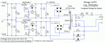
Hi Hiraga fans,
Have people used a cap. multiplier for this amp ?
I have found a cap mult by Juma (see attached) on a different Hiraga thread (the 20W version),
I have modified some value to suit my need (aiming for 10W/ch) at +/- 14Vdc.
Any comments..still debating about the use of a regular CLC or the cap. multiplier, if anyone had a listen with both type please share your thoughts.
The 15Vac secondary seems high but it's to account for the voltage drop of the bridge and the voltage drop when the transformer is loaded. (Not sure about Triad's regulation...)
Thanks,
Eric
Attachments
Last edited:
Hi Guys I have a couple questions. I kind of tried to set this up with what I had in the bin. I didn't have 470ohm or 100ohm trimmer so I installed a 200ohm. I used the 390R resistors. The only transistors I had that matched the pinout on the boards I etched were KSC1845/KAS992 so that's what I used. I installed 2sk246/2SJ103 fets, and MJL21193/MJL21194 for the outputs. I'm getting about 365mA bias, (365mV across one 1R resistor). There is no output. Is the bias just too low or is there something else I should be looking for. Vbe looks OK on all the BJTs. I'm not familiar enough with JFETs to know how to check those.
Thanks, Terry
Thanks, Terry
Sorry about the earlier post. I was bitten by the device pic for the board I etched. the OP showed turning the FETs 180deg. Now that I am having problems I checked the pinout of the 2SK246/J103 and they do not need to be rotated. The silkscreen is correct as is. Tomorrow I will try rotating them as see if they work. Hopefully they weren't damaged. I'll report back.
Hi Terry,
Man you are quick, I like that ;-)
Dissi mentioned the following on p.119, did you consider it ?
''The new version using the JFETs 2SK246GR/2SJ103GR and a 470 Ohm trim-pot yields a current of approximately 2.7 mA in the input stage. For a quiescent current of 0.6 A a load resistor around 480 Ohm is appropriate. But there's a big problem with these JFETs. The forward transfer admittance is significantly lower and the voltage gain in the input stage only is 1 (-17 dB). Hence the new version clearly is inferior, a loss of 17 dB in open loop gain is way too much IMO.''
Rgds,
Eric
Yeah I read that. That's life I guess. I read through that other website again and realized the OP actually used the 2sk170 which does have a reversed pinout. I also see that he installed two 2K pots in parallel with 1k pots to set the bias. I did get a chance to try some different resistors to get closer to the 600mA bias. I'll probably install some pots tomorrow so I can find the resistor value needed to get the right current. If the amp sounds good enough I may look for the original parts.
Blessings, Terry
Blessings, Terry
- Home
- Amplifiers
- Solid State
- Hiraga "Le Monstre"