Not really enough inductance to be useful. These are for use in SMPS or as RF filters on line conditioners.
Shoog
Not really enough inductance to be useful. These are for use in SMPS or as RF filters on line conditioners.
Shoog
How much inductance should we look for?
Regards,
Sachin
Minimum would be in the mH range. These are all uH.
Shoog
I have found only few 1MH inductor with 2A or more.Are these any good?
1MH inductors
Regards,
Sachin
I have found only few 1MH inductor with 2A or more.Are these any good?
1MH inductors
Regards,
Sachin
Others will have to comment since I am more used to valve amps where 5H is a low value.
However Duncanamps PSU2 will tell you a lot about power supply design in a short order.
Shoog
has anybody tried using switching supply? (with a softstar type delay circuit on the output of course) That should reduce the requirement on uF by quite a lot.
But you then have to use low/ultra-low ESR caps, which ain't cheap.
But you then have to use low/ultra-low ESR caps, which ain't cheap.
need advice about hiraga 8 watt
Hello everyone. 'm new to the forum in fact this is my first post.
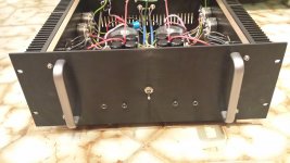
I recently built the version Le Monstre 8 watts.
I'm incredibly surprised by the sound of this amp and would like to get advice from experienced people like you who write in this thread.
I am not particularly electronics expert but all in all I get along pretty well with the soldering iron.
It worked right away and after adjusting the bias of the output transistors at 600mA it was possible to calibrate the offset to about 2mv for both channels.
I used new alternative transistor because i can't find the originals.
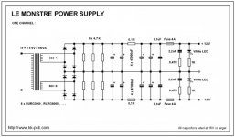
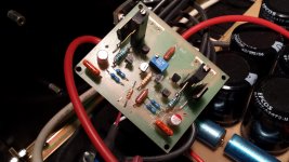
However , I am attaching the the pictures of the electrical configuration that I used for the power stage and for the output stage.
Add more photos of the unit.
I would be very happy to receive advice.
P.S. sorry if my english is not perfect !!!
Hello everyone. 'm new to the forum in fact this is my first post.
I recently built the version Le Monstre 8 watts.
I'm incredibly surprised by the sound of this amp and would like to get advice from experienced people like you who write in this thread.
I am not particularly electronics expert but all in all I get along pretty well with the soldering iron.
It worked right away and after adjusting the bias of the output transistors at 600mA it was possible to calibrate the offset to about 2mv for both channels.
I used new alternative transistor because i can't find the originals.
However , I am attaching the the pictures of the electrical configuration that I used for the power stage and for the output stage.
Add more photos of the unit.
I would be very happy to receive advice.
P.S. sorry if my english is not perfect !!!
Attachments
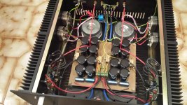
Nice neat build. Any hum left ?
Shoog
Not anymore. Before was present just a little hum, but now with shielded signal cables and star connected ground, the hum is totally absent.
Now i drive it with a conrad johnson evolution 20 and also with the volume pot at maximum level there isn't any hum.
I also tried it with a audible illusions modulus 3 and cause to the little big gain that it have, at the max volume pot, there was a little bit of hum, but just at the max volume.
thank you very much for your interest !!! 🙂
Hello everyone. 'm new to the forum in fact this is my first post.
I recently built the version Le Monstre 8 watts.
I'm incredibly surprised by the sound of this amp and would like to get advice from experienced people like you who write in this thread.
I am not particularly electronics expert but all in all I get along pretty well with the soldering iron.
It worked right away and after adjusting the bias of the output transistors at 600mA it was possible to calibrate the offset to about 2mv for both channels.
I used new alternative transistor because i can't find the originals.
However , I am attaching the the pictures of the electrical configuration that I used for the power stage and for the output stage.
Add more photos of the unit.
I would be very happy to receive advice.
P.S. sorry if my english is not perfect !!!
Very nice amp you got🙂! Congrats.
I like to use those Semikron bridges also.
Greetings
Very nice amp you got🙂! Congrats.
I like to use those Semikron bridges also.
Greetings
Thanks a lot! 🙂
regard to the bridges semikron, I used those because I had available and I have not had to buy.
In fact, according to the wiring diagram that I used, the bridges should be made with ultrafast diodes RURG3060 or RURG8060 and soft recovery.
Soon I will put them in place of semikron.
Do you have advice on this?
Nice design Camozzi.
How would you describe the sound compared to other amplifiers you have heard?
How would you describe the sound compared to other amplifiers you have heard?
Nice design Camozzi.
How would you describe the sound compared to other amplifiers you have heard?
Hello, thanks for the interest.
Respect to the sound this is the story:
My apparates are composed of a single ended 2A3 tube amplifier and a audible illusions modulus 3 preamp.
Speakers are also home-made and they are made with fostex fe 163 ENS according to the original fostex project.
I've always preferred the sound of the tubes and this amp I have almost made "for fun" and to do new experiences, but I honestly did not think that a SS unit so simple could play so well.
Has a very clean sound and three-dimensional, and is absolutely not tiring.
In a nutshell ... I had to think again about the ss!!!😀
I think that in some musical aspects, the 2a3 has no rivals, but this, perhaps, is the thing that comes close to it, just for the sound so sweet!
if I had only known the result, surely I would have done more attention to the choice of capacitor, spending a little more.
I think that soon I will build another one for bi-amping!!!
Bye!!!
1) Using SQP series resistors not good, better to use 5*MFR-2 1% 100 ppm (or better ppm)
2) Power lines must be go from one point.
3) You must to set LPF (for example 1k2+470 pF[WimaFKP or Mica], where capacitor).
4) 2k (potentials), 10om (feedback), 47k (input resist) resistors and cap of LPF go to one point of signal ground.
5) Power ground from bypass go to one point, this point to do under input point (signal ground) on 3 mm and connect them by thin line (width 0,4 mm)
6) Caps of bypass must be bigger than 47uF (220-1000 uF) and very good quality (as example Nichicon KZ, FG, KA or Elna Silmic II, ROA).
7) All resistors must be not worse than 0,5% 50 ppm (better to use 0,1% 15 ppm).
my findings:
re 1) If you are designing a PCB then it is handsome to be able to parallel the 1000 ohm collector resistor with a 5 kΩ Bourns . It makes life easier. I saw you glued a trimmer on the board!
re 6) No bypass also works.
Last edited:
Fighting instability in a Monstre
I redeployed a Le Monstre with the original printed circuits and the original active components in a new housing with a small footprint.
My first Le Monstre was a big cabinet of 40 cm high, 50 wide and 40 deep, filled with large can-sized Sprague electrolytics connected with big slabs of copper plate. And a big radiator for each channel. Weight: over 15 kgs. I ran over an ampere idle current at 14 volts.
Over the years I reduced the footprint. See for instance my posts where I implemented a shunt power supply.
Now I decided to reduce the size even further to fit in a commodity cabinet , and I decided to reduce as well the wattage. I need it to power a speaker with 96-98 dB sensitivity and having 15-20 ohms, where 3 watts in pure class A is enough, thus the 0,5 amp should suffice.
Changes I made:


When I fired up the boards with the new passive components I was treated on a very big ringing. It was even visible on the ground plane itself (lower trace). Changing the PS to passive had no effect. Changing the grounding did only change a little bit.

After quite some experimenting, I found out what the reason was that I had instability on the circuit boards.
I remembered that Nelson “papa” Pass once commented on a poster who complained about instability in his F5 and asking about the values of the decoupling capacitor, “who said I have decoupling in my design”. [The F5 is similar in concept to the Le Monstre; Chinese boards have place for such caps]

So, taking the decoupling caps out completely from the Le Monstre board made all instability disappear. Relooking at the published circuit by Hiraga, I saw that it mentioned 47 uF. Quite different from the diet of a meagre 220 nF that I had put my Monstre on!
As always, days of work from bad reworking of a design.

The final build: with 100 pF on the entrance to shoot all the overshoot out of the system.
DC power supply is flat with less than 0,15 mV RMS for plus and minus and the output also shows a last bit of 0,1 mV RMS due to earthing/cabling differences. Something to improve.
I redeployed a Le Monstre with the original printed circuits and the original active components in a new housing with a small footprint.
My first Le Monstre was a big cabinet of 40 cm high, 50 wide and 40 deep, filled with large can-sized Sprague electrolytics connected with big slabs of copper plate. And a big radiator for each channel. Weight: over 15 kgs. I ran over an ampere idle current at 14 volts.
Over the years I reduced the footprint. See for instance my posts where I implemented a shunt power supply.
Now I decided to reduce the size even further to fit in a commodity cabinet , and I decided to reduce as well the wattage. I need it to power a speaker with 96-98 dB sensitivity and having 15-20 ohms, where 3 watts in pure class A is enough, thus the 0,5 amp should suffice.
Changes I made:
- I decided to treat myself with some very nice resistors this time to replace some old wire-wound ones for the feedback: I selected a Caddock MP825 200 Ω flat film and a Tyco MPC 10 Ω thick film resistor. I also bought Caddock MP850 1 Ω for the emitter resistors in the output. All utterly non inductive.
- I paralleled the 1000 Ω resistors in the first stage (on the collectors) with 5 kΩ(just like the F5) for easy setting of the output current. A very recommended improvement.
- I put in some nice 220 nF mylar decoupling capacitors too instead of the large 36 uF solid tantals paralleled with extra decoupling with polypropylenes I used to have - I now needed something definitely small.
- I decided this time to go with an active power supply (A Hiraga design implemented around a LM431/2SK135/2SJ50, with less than 0,3 mV noise).
When I fired up the boards with the new passive components I was treated on a very big ringing. It was even visible on the ground plane itself (lower trace). Changing the PS to passive had no effect. Changing the grounding did only change a little bit.
After quite some experimenting, I found out what the reason was that I had instability on the circuit boards.
I remembered that Nelson “papa” Pass once commented on a poster who complained about instability in his F5 and asking about the values of the decoupling capacitor, “who said I have decoupling in my design”. [The F5 is similar in concept to the Le Monstre; Chinese boards have place for such caps]
So, taking the decoupling caps out completely from the Le Monstre board made all instability disappear. Relooking at the published circuit by Hiraga, I saw that it mentioned 47 uF. Quite different from the diet of a meagre 220 nF that I had put my Monstre on!
As always, days of work from bad reworking of a design.
The final build: with 100 pF on the entrance to shoot all the overshoot out of the system.
DC power supply is flat with less than 0,15 mV RMS for plus and minus and the output also shows a last bit of 0,1 mV RMS due to earthing/cabling differences. Something to improve.
Nice, can you please describe your ps? Also do you mean your final snap is from no decoupling cap condition?
Sent from my iPad using Tapatalk HD
Sent from my iPad using Tapatalk HD

Le monstre input sensivity
Hello guys.
I write to get an information (as soon as possible) about the input sensitivity of my Le Monstre.
The question is this: in an appropriate manner by varying the input resistors (1.2k - 47k), can I REDUCE the input sensitivity?
There might be some contraindication for the remaining part of the circuit?😕
Greetings to All!
The schematic that I used is the following:
Attachments

- Home
- Amplifiers
- Solid State
- Hiraga "Le Monstre"