More details in Linear Audio to come, this was actually the topic that caused me to write the previous articles, just to lay the theoretical foundations to cover this properly, unfortunately could not finish it in time for the 8th issue.
Best wishes
David
Space reserved!
Jan
I am clueless about the latter including Ergodic Theory if that's what is referenced?
Non-energic is not the same as non-ergodic, the confusion is not helped by the fact that Birkhoff invented the first term, in 1927, and then did fundamental work on the second a few years later. I should have included a date reference.
Nonenergic feedback is feedback implemented with lossless components only, transformers, inductors and capacitors and so on.
That means you have conservation laws and thus can use the whole arsenal of 300 years of mathematical techniques for conservative systems like mechanics.
I have just touched the start of this, it has an obvious theoretical appeal and should provide limits to what is possible.
Not sure if that is worth the effort, especially when in practice, of course, I don't want to have feedback transformers.
They would probably appeal to a certain niche.😉
Space reserved!
Thanks Jan, sorry I didn't have it ready in time for September edition.
Best wishes
David
Last edited:
Douglas,
I might get lambasted for this, but do you accept that something that may not be measurable may in fact sound different or better?. I recall Nelson Pass talking about the global feedback being taken off of the Stasis, placed from the Vas to inverting input, measuring the same yet sounding "better".
Colin
Fig1c is "output inclusive"...................
Yes, hence my earlier comment that we need to separate the terms "TMC" from "output inclusive" ...........
and it can be seen that it is not TMC.
Douglas,
I might get lambasted for this, but do you accept that something that may not be measurable may in fact sound different or better?. I recall Nelson Pass talking about the global feedback being taken off of the Stasis, placed from the Vas to inverting input, measuring the same yet sounding "better".
Colin
I've always been intrigued by such reports. Surely we can agree that ANY audible difference results from different electrical waves at the speaker terminals; I hope we will exclude extra-sensory perception!
So we would have an audible difference between two wave shapes that measure the same. The only possible conclusions* are 1) we hear more sensitive than we can measure or b) we're measuring the wrong (or at least not relevant) things.
Considering the huge evidence we can set 1) aside as very unlikely, so the remaining option is we measure the wrong thing.
One thing I never see measured is amplifier performance right after a large burst or a strong passage. I have read the reports by the usual suspects (DS, BC come to mind) on thermal transients in output stages, for instance, but my own research indicates that within the stable bias condition over a longer period, sub-second variations in bias current can exists that are 'smoothed out' in the average bias measurements. What if a soft passage is reproduced just after a strong passage that shifted the bias, before the bias loop has returned to the rest position?
Anybody has any experience with such things?
Jan
*I am assuming for the moment that the reported audible difference is objectively, repeatably there, which of course is another oil drum of worms, but for another occasion perhaps...
Last edited:
One thing I never see measured is amplifier performance right after a large burst or a strong passage. I have read the reports by the usual suspects (DS, BC come to mind) on thermal transients in output stages, for instance, but my own research indicates that within the stable bias condition over a longer period, sub-second variations in bias current can exists that are 'smoothed out' in the average bias measurements. What if a soft passage is reproduced just after a strong passage that shifted the bias, before the bias loop has returned to the rest position?
Anybody has any experience with such things?
It's actually quite well-known in the tube world, though the mechanisms are different. Crowhurst wrote extensively about it in the 1950s, and both Morgan and I have designed amps (Crystal Palace and Red Light District, respectively) taking this explicitly into account.
Coupling and bypass caps, especially at cathodes- like I said, different mechanism, same effect.
This is, I suspect, the explanation for why TMC can work better than TPC, despite the "mathematical" equivalence that is often expounded.
Another way to look at it is that TPC has a "lossy" shunt to earth, TMC is "lossless" in some sense.
Please define "TMC can work better". If you mean TMC can provide higher loop gains, that's incorrect in any apple to apple comparison. The FDNR is there, but it can be safely ignored in any non-pathological, practical, case. Caring for that FDNR sounds like Mr. Zan caring about audio amplifiers being non-minimum phase systems, because of the bipolar beta RHP beyond Ft, at some 500 MHz. Come on...
Anyway, I know somebody in Canada that will get pretty angry if you don't properly cite prior art in the TMC vs. TPC equivalence 😛. Expect a letter to the Editor 😀.
TPC "lossy" and TMC "lossless"? You lost me here.
No, it's not those "loop gain probe" thesis guys I'm working for. I built the probe, using a commercially available pulse transformer, for measuring the loop gain and stability margin of a mixed signal IC library, bicmos wideband, two pole compensated, opamp. Works fine for 1KHz up to 6-7MHz.
Not sure I follow the question. Z1 is a capacitor in the output inclusive compensation network. Fig. 1C is not what we call "output inclusive", or TMC, herein
I would say that my Fig 1C is attempting to be output inclusive compensation- but it will almost certainly be unstable because of the extra phase-shifts in the output stage.
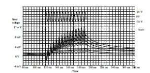
Example from a VAS in open loop. Of course you won't see that with loop closed. Does that mean it isn't there anymore?
Jan
Jan, can you post a bigger version of that plot?
started on a free SW based update of the equations that could be shared - still fighting with how XCAS works
but this should give the flavor - and show the Zab element has the nonphysical FDNR Frequency Dependent Negative Resistance element - which can be considered as "explaining" the "extra" gain from splitting, bootstrapping
in the last 3 lines I resort to some hand entry to massage the symbolic results for near readibility
Looks good/familiar 🙂, manually it is simpler to put the conclusion ahead (2 pole equivalence), calculate the impedances for TPC, then identify the coefficients. Then see what's left (like the FDNR, etc...), analyze the physical interpretation (if any) and check if their magnitude and phase are anywhere relevant in the particular circuit topology. That's how I did it, and for common 3 stage amplifier topologies (either Blameless or the derived symmetrical) the equivalence is in the % range.
I know Edmond has some special designed topologies where the TMC can have a significant advantage over TPC. Those look interesting, but still have to be experimented and evaluated on a board. My experience with Edmond's auto bias was a disaster (in terms of stability), so I take all his extreme designs with a big grain of salt.
I would say that my Fig 1C is attempting to be output inclusive compensation- but it will almost certainly be unstable because of the extra phase-shifts in the output stage.
Yes, since Cheery 😀.
When you search google " halcro amplifier circuit diagram " " pictures " you find more.Patent US5892398 - Amplifier having ultra-low distortion - Google Patents
Ah yes, I am very familiar with that review; many thanks. However the Halcro is not much help to us as it is a highly unconventional (and very complicated) design. I should have said that I was thinking of more conventional designs, and especially the differences in distortion performance between single-ended and push-pull VAS's.
BTW, anyone know precisely what happened to Halcro? The "latest news" on their website is dated 2010, so it doesn't look good.
Last edited:
I should have said that I was thinking of more conventional designs, and especially the differences in distortion performance between single-ended and push-pull VAS's.
For high power (= high and symmetrical slew rate) I prefer complementary differential input and push-pull VAS, rather than SE VAS + CCS.
Once you include (mathematically) complex impedances the calculated equivalent networks may not be both equally physically realizable.
In particular, a realistic star network of capacitors and resistors may have a equivalent delta transform that contains non-physical components like -ve resistors.
So there are implementation issues that are not trivial.
If I understand correctly, this delta-wye transform business is crucial to the "Output-Inclusive Compensation is a form of TPC" battle cry. But if it yields non-physical components it seems to me of little use in understanding things. I'm not afraid of FDNR's (or worse) but I would hesitate to design them into an amplifier.
I was hoping that someone could tell us exactly how this theory helps with practical amplifier design.
Jan, can you post a bigger version of that plot?
Attachments
- Status
- Not open for further replies.
- Home
- Amplifiers
- Solid State
- Your opinions are sought on Audio Power Amplifier Design: 6th Edition. Douglas Self