Well, you've been shown where you went wrong, but you still seem to want to argue about it. My version has been keeping VAS transistors intact for at least twenty years, in mass-production for four different manufacturers. This adds up to tens of thousands of units. I call that a proven circuit.
Wrong. Be kind to your VAS transistor.
I think our work on this topic is done.
OK it is done since you don't accept my arguments and don't want to do the simulation by yourself.
BR Damir
Mr. Self, it is very, very hard to explain this without making use of lots of algebra, and this forum is not formulae friendly. Anyway, here's the basic plot.
Hello Waly
Many thanks to you for taking the trouble to post that. I am glad I managed to grope my way to at least part of the explanation. I think I had better go off now and go some sums and some sims.
Are you by any chance a fan of David Baerwald?
Are you by any chance a fan of David Baerwald?
Nope, never heard about. If it belongs to your generation, I'm more like a fan of our very own indies Portishead and PiL (of John Lydon extraction).
Last edited:
Nope, never heard about. If it belongs to your generation, I'm more like a fan of our very own indies Portishead and PiL (of John Lydon extraction).
Ah well, wrong again. Your sig line made me think of this:
https://www.youtube.com/watch?v=6qG-SCiGckY
BTW, where are you in London?
Going back to the Rotel RB-1080, it would be very useful to find other examples where:
1) Stereophile have measured it and published the results
2) The schematic is available to download
3) The amplifier in question has a direct input to the power amplifier stage.
This would allow some more very useful correlations to be made between circuit configurations and performance.
Obviously rooting through the piles of material to find amplifiers where all three requirements are met is going to be quite the undertaking. I wonder however if anyone has any other examples to hand.
When you search google " halcro amplifier circuit diagram " " pictures " you find more.Patent US5892398 - Amplifier having ultra-low distortion - Google Patents
Here is the review and the measurements :Halcro dm88 Reference monoblock power amplifier Measurements | Stereophile.com
Ah well, wrong again. Your sig line made me think of this:
https://www.youtube.com/watch?v=6qG-SCiGckY
BTW, where are you in London?
No longer in London now... was in Acton. Now doing an internship abroad. The sig line is a quote from a diyaudio forum renowned audio designer, I kinda like it when he said "You are nobody".
No longer in London now... was in Acton. Now doing an internship abroad. The sig line is a quote from a diyaudio forum renowned audio designer, I kinda like it when he said "You are nobody".
C'mon, spill the beans, which nasty bit of work was it said that? Seems to me you know what you are talking about.
You can email me; address on front page of my website.
Last edited:
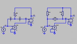
At the risk of embarrassing myself, is this what you're describing? I'm afraid I'm struggling to see what Z1 refers to in the output-inclusive case, other than infinite impedance?Draw the VAS as a gain stage of transconductance -Gm and load Z (which, in this case, you may assume is resistive) and the output stage as an ideal voltage amplifier of gain +1.
An externally hosted image should be here but it was not working when we last tested it.
An externally hosted image should be here but it was not working when we last tested it.
Last edited:
At the risk of embarrassing myself, is this what you're describing? I'm afraid I'm struggling to see what Z1 refers to in the output-inclusive case, other than infinite impedance?
An externally hosted image should be here but it was not working when we last tested it.
An externally hosted image should be here but it was not working when we last tested it.
Not sure I follow the question. Z1 is a capacitor in the output inclusive compensation network. Fig. 1C is not what we call "output inclusive", or TMC, herein
Last edited:
Ah, that explains my puzzlement. Found my answer here:. Fig. 1C is not what we call "output inclusive", or TMC, herein
http://home.tiscali.nl/data.odyssey/Super_TIS.html
Above link is no longer valid (since today?) Please use this one:Ah, that explains my puzzlement. Found my answer here:
http://home.tiscali.nl/data.odyssey/Super_TIS.html
Super TIS
Cheers, E.
I would have 1st seen, and then did duplicate for myself in Mathcad... Ovidiu Poppa analysis on the now dead site
I started only after that site was dead, hence my uncertainty on the history.
Also meant I had to work it out from scratch, but this was very educational so probably a positive.
Mr. Self, it is very, very hard to explain... Anyway, here's the basic plot...
Sorry, this is all I can help with.
Fair summary, but there is an important subtlety that needs to be understood.
Your reference provides all the formulae in terms of R, by implication resistances.
Once you include (mathematically) complex impedances the calculated equivalent networks may not be both equally physically realizable.
In particular, a realistic star network of capacitors and resistors may have a equivalent delta transform that contains non-physical components like -ve resistors.
So there are implementation issues that are not trivial.
More details in Linear Audio to come, this was actually the topic that caused me to write the previous articles, just to lay the theoretical foundations to cover this properly, unfortunately could not finish it in time for the 8th issue.
P.S. AndyC... *please* reopen that forum, at least for read only
Second that.
...an internship abroad.
Is that with the people who did the loop probe thesis?
If so then pass them my compliments, nice piece of work and thanks for the link.
Not sure I follow the question. Z1 is a capacitor in the output inclusive compensation network. Fig. 1C is not what we call "output inclusive", or TMC, herein
Yes, hence my earlier comment that we need to separate the terms "TMC" from "output inclusive"
Best wishes
David
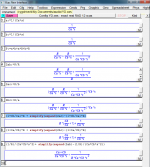
started on a free SW based update of the equations that could be shared - still fighting with how XCAS works
but this should give the flavor - and show the Zab element has the nonphysical FDNR Frequency Dependent Negative Resistance element - which can be considered as "explaining" the "extra" gain from splitting, bootstrapping
in the last 3 lines I resort to some hand entry to massage the symbolic results for near readibility
Attachments
Last edited:
...
and show the Zab element has the nonphysical FDNR Frequency Dependent Negative Resistance element - which can be considered as "explaining" the "extra" gain from splitting, bootstrapping
Exactly! I planned to keep that bit for Linear Audio, now you've spoiled the surprise😉 Luckily, I think we're alone here.😉
This is, I suspect, the explanation for why TMC can work better than TPC, despite the "mathematical" equivalence that is often expounded.
Another way to look at it is that TPC has a "lossy" shunt to earth, TMC is "lossless" in some sense.
I found a few references to non-energic feedback [1], defined rather obscurely (at least to me), that I suspect is another way to express this, you know about this?
Best wishes
David
[1] Birkhoff.
Last edited:
I'm sure there's still plenty of scope for a great article
I am clueless about the latter including Ergodic Theory if that's what is referenced?
I am clueless about the latter including Ergodic Theory if that's what is referenced?
You're welcome, Pavel. I hope you have enjoyed this web page.
Cheers, E.
Yes Edmond, very nice job.
- Status
- Not open for further replies.
- Home
- Amplifiers
- Solid State
- Your opinions are sought on Audio Power Amplifier Design: 6th Edition. Douglas Self