Do I accept that there are real subjective differences when the electrical waveforms are identical? No, of course not. What are you proposing, black magic?Douglas,
I might get lambasted for this, but do you accept that something that may not be measurable may in fact sound different or better?
Imaginary subjective differences? Yeah, all the time.
I recall Nelson Pass talking about the global feedback being taken off of the Stasis, placed from the Vas to inverting input, measuring the same yet sounding "better".
If this means that putting the output stage outside the NFB loop did not change the distortion measurements, then I find that very hard to believe.
One thing I never see measured is amplifier performance right after a large burst or a strong passage. I have read the reports by the usual suspects (DS, BC come to mind) on thermal transients in output stages, for instance, but my own research indicates that within the stable bias condition over a longer period, sub-second variations in bias current can exists that are 'smoothed out' in the average bias measurements. What if a soft passage is reproduced just after a strong passage that shifted the bias, before the bias loop has returned to the rest position?
Anybody has any experience with such things?
Jan
Usual Suspect reporting.
Jan, I'm sure you are aware of my plots of distortion over time for an under-biased output stage. (APAD6 p536 etc) This is a great way to measure bias changes over seconds, which should handle the "soft passage reproduced just after a strong passage" case, but the AP does not make measurements fast enough to show sub-second variations. On the other hand, THD tests at 10 Hz do not suggest any significant bias changes over a cycle.
Something that is often overlooked is that even perfect temperature compensation of Class-B bias does not mean the bias is constant. The quiescent current and Vq are also affected by the collector voltages on the driver and output devices, and hence by the mains voltage. (APAD6 p533 etc) Variac-ing the mains up and down by 10% shows clear changes in the THD residual.
Thanks for posting the big picture. I am however a little puzzled as to what exactly "thermal error" is. Could you explain a bit more?
Last edited:
a big grain of salt??
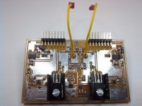
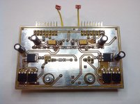
"Against my expectations the SuperTIS is a very stable and rugged Frond End - even with a horribly fast OPS, slight capacitive load and OPS-rail switching. Unfortunately I haven't saved the oscilloscope screens but you can find two pictures of the SuperTIS board attached to this E-Mail."
Cheers, E.
PS1: Normally, people contact me if they have troubles with my designs. You are invited to do this as well.
PS2: The schematic of the front-end can be found here:http://home.telfort.nl/data.odyssey/Super_TIS.html Fig. 6
The SuperTIS has been built and tested by Philipp Gutknecht (see pics). I'm still waiting for a full report of his findings. In the meantime he wrote me:[..]
I know Edmond has some special designed topologies where the TMC can have a significant advantage over TPC. Those look interesting, but still have to be experimented and evaluated on a board.
"Against my expectations the SuperTIS is a very stable and rugged Frond End - even with a horribly fast OPS, slight capacitive load and OPS-rail switching. Unfortunately I haven't saved the oscilloscope screens but you can find two pictures of the SuperTIS board attached to this E-Mail."
This is the first time you told us this. Have you just simmed it or really built it ? If just simmed, (I'm sorry to say so) it not the first time you have produced erroneous result. If built, please show us the details (schematic, list of components, PCB and measurement results).My experience with Edmond's auto bias was a disaster (in terms of stability), so I take all his extreme designs with a big grain of salt.
Cheers, E.
PS1: Normally, people contact me if they have troubles with my designs. You are invited to do this as well.
PS2: The schematic of the front-end can be found here:http://home.telfort.nl/data.odyssey/Super_TIS.html Fig. 6
Attachments
Last edited:
Thanks for posting the big picture. I am however a little puzzled as to what exactly "thermal error" is. Could you explain a bit more?
Douglas I will send you some stuff off-line. The pic I posted is not my own but from a book written by another author I am preparing. But I also have some data from own measurements.
Jan
My experience with Edmond's auto bias was a disaster (in terms of stability), so I take all his extreme designs with a big grain of salt.
Waly,
Which of Edmonds Autobias designs did you try? Only asking as I am preparing to prototype an amp using a modified version of his AB2ECV4. May save my sanity if I know in advance if it's going to be "fun" to get working.
Seems to work ok in sims...
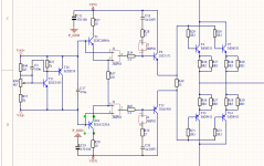
AB2ECV4
Paul
Hi Paul,
Which trannies are you planning to use? For Q3...Q10 you will need matched trannies anyhow, that is, PNP to PNP and NPN to NPN (e.g. THAT300 resp. THAT320).
Cheers, E.
Which trannies are you planning to use? For Q3...Q10 you will need matched trannies anyhow, that is, PNP to PNP and NPN to NPN (e.g. THAT300 resp. THAT320).
Cheers, E.
Hi Paul,
Which trannies are you planning to use? For Q3...Q10 you will need matched trannies anyhow, that is, PNP to PNP and NPN to NPN (e.g. THAT300 resp. THAT320).
Cheers, E.
Hi Edmond,
Plan to use the suggested transistors (THAT300, THAT320) for those positions.
Expensive but saves matching transistors.
As usual my stumbling block is analysing the loops... But have found that omitting R6,7 makes things more stable. At least in sims.
Paul
Ah yes, I am very familiar with that review; many thanks. However the Halcro is not much help to us as it is a highly unconventional (and very complicated) design. I should have said that I was thinking of more conventional designs, and especially the differences in distortion performance between single-ended and push-pull VAS's.
Fundamentally, in the Halcro, despite their sophistication, the input-stage (differential of Sziklai pairs, twice-cascoded, current mirror) and VAS (single-ended, cascoded) are of the same two-stages topology as the Blameless.
This VAS is a proof that a single-ended stage here does not constitute a limit in the search of extremely low distortion.
This is the first time you told us this. Have you just simmed it or really built it ? If just simmed, (I'm sorry to say so) it not the first time you have produced erroneous result. If built, please show us the details (schematic, list of components, PCB and measurement results).
Ask your BFF syn08, he built it. I understand the superTIS is indeed fine, but it appears to be designed just for proving that TMC can, in a particular case, do better than TPC. Overall, that's nothing outstanding in the superTIS performance, compared to a standard design with CMCL.
However the autobias output stage (the latest, as far as I understand, I suppose from here) built with vertical mosfets was experiencing transient instability issues that makes it unusable. If I recall correctly you got this in simulation, when you mentioned that the autobias has pretty bad transient response, that required limiting the maximum slew rate in the input signal. It appears that in practice is much worse than in the simulator (not really unexpected). The autobias output stage bias stability is very good, and as far as it doesn't start oscillating and subsequently latch up due to a fast input signal, the distortion performance is very good. It always happen only when the input signal is high (but still far away from clipping), even without any front end (input stage + VAS).
That is not surprising, I see your autobias (which is pretty much a high speed version of the Linear Technology LT1166) as just another error correction output stage, where the loop gain is created by a positive feedback network. If you could tame that transient instabilities in the output stage core, it would be worth exploring further, otherwise it will remain only of theoretical simulation interest...
That's all I know about, and please don't argue with me about these results, I'm only the messenger.
P.S. syn08 also used THAT matched devices in his implementation.
P.P.S I don't plan building any of your designs - I prefer to put my very limited resources in something else.
Last edited:
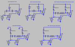
the Y-Delta Transform is useful for simplifying analysis by changing the equivalent circuit's topology to only have simple, nonintersecting loops
the Delta equivalent only has separable loop feedback branches
for the split C, R "T" used for both 2-pole and TMC the FNDR appears in the transformed Y circuit regardless of the connections at the ends
TMC/OIC only differs from 2-pole by the connection of the R to either the output or gnd
the FDNR appears in exactly the same circuit position in both - in the single series local feedback branch across the VAS
with the same VAS local feedback branch both are very similar, the local feedback defines a region of 2nd order VAS stage gain in both cases
2-pole does have Zac,bc shunt loads on VAS input and out dragging down the gain a bit vs TMC with the same component values
TMC with exactly unity gain output stage bootstraps away the Zbc branch across the output reducing VAS loading vs 2-pole
the VAS in TMC has the same local feedback, provides the same 2nd order gain to the output stage
the Zac becomes a outer feedback from the output stage back to the VAS input, giving the "single pole" appearance of TMC's nested loops when viewed as global open loop gain
Attachments
Last edited:
Adding a zero
Hi Paul,
>But have found that omitting R6,7 makes things more stable. At least in sims.
Might be, but much depends on circuit details, and not unimportantly, which loop you are talking about? Anyhow, these two resistors creates a zero. Thus, normally, they should increase the stability (of course, there are exceptions). In later designs I've replaced C2/C3 by 470pF and R6/7 by 56 Ohms. Then, as for the FB loop around the OPS itself, the phase margin (simmed) is 88 degrees @ 3MHz (under idle conditions). Hope this helps.
Cheers, E.
I read and enjoyed one of your poweramp books a few years ago (borrowed from a friend). Not sure which edition. I loved your emphasis on dealing with crossover distortion with the push-pull output stage. I find that many conventional tube type P-P output stages will have substantial crossover distortion when pushed into clipping, which I don't like. I use tubes for my guitar amps and use overdrive distortion for effect, and crossover distortion isn't good distortion IMO. I know of one topology that appears to do that much less. I've always thought that a really good poweramp should have a compressor/limiter that keeps it from ever clipping (very fast attack time), and is completely inactive below the half or quarter power point. Also a passive Rf filter at the input (you probably had that - can't remember - so many amps don't).
I would say that my Fig 1C is attempting to be output inclusive compensation- but it will almost certainly be unstable because of the extra phase-shifts in the output stage.
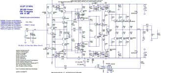
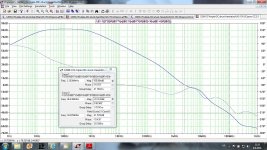
In spite to be rejected again, I think that Inclusive Output Compensation, in this case in combination with shunt compensation, could be used and be very stable. This amp is with Phase Margin of 70 degree and Gain margin of 40 dB. This is so called CFA with not so low distortion as with a VFA with less components, but looks very stable at least in the simulation.
BR Damir
Attachments
Last edited:
Doug,
Black magic, no, but I'm still working on that voodoo science to extract the unmeasurable quality of scientifically Un achievable sound 🙂. I suppose I'm grappling with the concept that the lowest thd measurement does not neccessarily lead to the best sounding amplifier. Do you listen to a lot of music. Doug?
Colin
Imaginary subjective differences? Yeah, all the time.
How have you determined the differences are imaginary and not due to placebo?
I suppose I'm grappling with the concept that the lowest thd measurement does not neccessarily lead to the best sounding amplifier.
I agree that good distortion measurements are only a necessary condition but not a satisfactory condition for a good sounding amplifier. Nonlinear distortion over audio band is just only one parameter. IMO, the fight for lowest distortion numbers is useless, the nonlinear distortion in isolation, below certain level (which I do not intend to define 🙂), is inaudible. Nonlinear distortion is IMO definitely not the sole parameter that defines resulting sound. Some have another view and exaggerate its influence. Differences between amplifiers with vanishingly low nonlinear distortion still exist and can be found by listening tests (even DBT). Level of sensitivity of different listeners is very different. I do not intend to start old quarrels, I am just telling my experience.
Doug,
Black magic, no, but I'm still working on that voodoo science to extract the unmeasurable quality of scientifically Un achievable sound 🙂. I suppose I'm grappling with the concept that the lowest thd measurement does not neccessarily lead to the best sounding amplifier. Do you listen to a lot of music. Doug?
Colin
It is a matter of taste, I play a tube amp on my bass because the sound is sweet compared to a solid state amp in this application...
IF you want to use the amp to color your sound it is a fair statement that the amp with the lowest THD may not be the one with the sweetest sound.
If I want sweet distorted sound on my audio system, I will build a devise that colors the sound to my liking. But I think the amp should be as transparent - in electrical terms - as possible.
When I play my bass the amp is very much part of my sound - I like that. When I play music at home I want my amp and system to be neutral and to reproduce the original sweetness from the recording - not add anything extra.
\\\Jens
Jan, I'm sure you are aware of my plots of distortion over time for an under-biased output stage. (APAD6 p536 etc) This is a great way to measure bias changes over seconds, which should handle the "soft passage reproduced just after a strong passage" case, but the AP does not make measurements fast enough to show sub-second variations.
The other approach is to prepare time domain distortion residual measurement with notch filter tuned at specified frequency, differential amplifier and oscilloscope. Then just turn on and turn off the sine wave and look if the distortion residual wave on the scope remains the same. It does not, and what you see is the changing bias with transistor temperature. It is almost impossible to build a thermal compensation that would be fast enough to follow and compensate sudden Vq/Iq thermal transients.
In my case I designed some circuitry to directly measure bias current under music conditions. That allows me to directly see bias movements related to signal levels, instead of distortion with levels.
I looked at the max bias shifts and then did separate THD measurements with the min and max bias. Conclusions were that bias may wander up to 8% or so but that such a change in bias is hardly measurable in THD numbers. As such the outcome was pretty much the same as Doug measured, confirming my method (or his method, depending 😉.
BUT, does that mean that therefore such a wavering is not audible?
Anyway, what I really would like to do, is to look at the internal open loop linearity changes with those bias changes, but that will not happen this year. I always have those long-range projects - the direct bias measurement has been gestating for three years...😱
Jan
Jan
Please define "TMC can work better".
Lower distortion at similar stability or better stability at similar distortion, for the same complexity. Or some trade-off of these criteria.
...sounds like Mr. Zan caring about audio amplifiers being non-minimum phase systems, because of the bipolar beta RHP beyond Ft, at some 500 MHz. Come on...
You seem to have misunderstood me. In our earlier discussion I pointed out some non-minimum phase behaviour but it had no connection to bipolar beta RHP beyond Ft.
It was caused by Miller compensation capacitor feed forward, a quite different effect.
I am reluctant to reference Bob Cordell's book for a second time in Mr Self's thread, but there is a succinct explanation there on p 176.
It is possible for this zero to move sufficiently low to make some difference if the transconductance of the IPS and the transconductance of the "VAS" are both simultaneously set to values that are atypical but feasible.
I pointed it out because it was so contrary to my own expectations, and I never understood why you disputed so vehemently rather than simply looked at the Bode plot where the effect was quite clear.
I am happy to have had a chance to clear this up.
... if you don't properly cite prior art in the TMC vs. TPC equivalence...
Why would you think I would do this? My very first post on the subject disclaimed priority. I have previously been it touch with Ovidiu and asked if he still had a copy of his derivation but had no luck. And I have asked Bob Cordell to ask Andy to re-open the site, also no luck. I would still like to read a copy.
TPC "lossy" and TMC "lossless"?
Simple shunt compensation "throws away" gain, whereas Miller compensation doesn't "waste" it, as explained in Mr Self's excellent book.
Gain is "lost" in shunt compensation, and similarly in TPC versus TMC.
I have not yet come up with a precise formulation of this concept, open to ideas. Attempts to express this mathematically were what lead me to "non-energic feedback" references. Too obscure to be useful so far.
Best wishes
David
Last edited:
- Status
- Not open for further replies.
- Home
- Amplifiers
- Solid State
- Your opinions are sought on Audio Power Amplifier Design: 6th Edition. Douglas Self