Again, simulation does not show any distortion when I use this clipper at the input.
I am not sure how to set the limiting voltage. (As is it hard clips at 2.2v)
Also BAT54 is a schottky diode... why does it appear as a zener in LTSpice ?
Every diode is a zener diode (even the 'diodes' that make a transistor).
RC, this is coming along very nicely. Some good thinking and sound decisions.
In my case I did see in my simulations quite a bit of benefit from the 3-device input stage. I'm not sure why you are not seeing it, but I suggest you play around it with it in your sims a bit more. Not suggesting you go back to this more complex approach but it might be nice to understand it further.
Why do you need the clipper again ? - the pcb layout and interpreting the sound/performance will be easier with the simplest circuit. Simulations make it too easy to add parts 🙂
I did play with it but am having difficulties understanding how it works and also it only sims ok if I use quite high miller caps..... In that case it eliminated 2nd harmonic and all others are lower than the single pole schematic so I am planning to leave space for this implementation latter.
My first build (The opamp input Nobrainer) has a very wide bandwidth and sounds quite pleasing but lacks power. Anyway, it promptly blew one channel when I unplugged the input rca when it was on.
That is why I want some kind of limiter.
Member
Joined 2009
Paid Member
I don't think you want a clipper, you may prefer to leave this out of the design for now. Perhaps it's better to think about how unplugging an rca broke a channel on your other amp (was it really just a spike - which would only produce clipping, or was it unstable oscillations?) and whether that is really likely to happen with this new design ? I believe you can make your new design robust without a clipper on the input.
THD is badly affected by the presence of the clipper circuit on the input.
Yes, that is what a clipper does (it clips) and a soft clipper is the worst (of all) 🙂 🙁
I did play with it but am having difficulties understanding how it works and also it only sims ok if I use quite high miller caps..... In that case it eliminated 2nd harmonic and all others are lower than the single pole schematic so I am planning to leave space for this implementation latter.
My first build (The opamp input Nobrainer) has a very wide bandwidth and sounds quite pleasing but lacks power. Anyway, it promptly blew one channel when I unplugged the input rca when it was on.
That is why I want some kind of limiter.
In that case a clamp to the op-amp rail would do the job, with no measurable side effects (a 1n4148 is 7pF, adding 2 (to clamp to the positive and negative rail) ads 14pF parallel to the input). Get one of the (or both) D. Self or B. Cordell power amp books.
THD is badly affected by the presence of the clipper circuit on the input.
What mosfet(s) where you using (as I noted the irf(9)240 is not a good choice, Vgs is to high, Cgate is to high, Cds is to high). Did you ever test with different source impedances (say 1 Ohm and 2k Ohm)?
In my opinion, the right approach to clipping is something like this - Apex BX-500 - a bit more complicated, but gives much more linearity, precision and control. Plus a cool led clipping indicator 😉
Anyway, normally you need it for powerful stage amplifiers - you most likely use them at high powers and can reach the limits easily. In my home setup, having 7 channels, roughly 100W each, I never reach the clipping point. Just no way. Something in the room may be damaged when it clips 🙂
Anyway, normally you need it for powerful stage amplifiers - you most likely use them at high powers and can reach the limits easily. In my home setup, having 7 channels, roughly 100W each, I never reach the clipping point. Just no way. Something in the room may be damaged when it clips 🙂
Last edited:
In that case a clamp to the op-amp rail would do the job, with no measurable side effects (a 1n4148 is 7pF, adding 2 (to clamp to the positive and negative rail) ads 14pF parallel to the input). Get one of the (or both) D. Self or B. Cordell power amp books.
Will do for the Nobrainer.
As for the Assemblage, I will leave it out for the moment.
Let us refer now to post 34 http://www.diyaudio.com/forums/solid-state/258549-assemblage-power-amp-4.html#post3982709
What miller cap should I aim at ?
This amp seems so stable that I could use as low as 10p.
I simulated for 22p 48p and 100p and see no hint of oscillations.
What miller cap should I aim at ?
This amp seems so stable that I could use as low as 10p.
I simulated for 22p 48p and 100p and see no hint of oscillations.
After reading Self papers and pushed by Ingram I am now considering implementing a 2 pole compensation but with a single VAS transistor.
Results seem promising. Files latter
Results seem promising. Files latter
Member
Joined 2009
Paid Member
Hi Ingram... why did you use the extra transistor in your final version ?
I wanted to try an input stage with more than single input and single VAS. It's quite common to use an emitter follower (EF) buffer in front of the VAS device, some call it an 'enhanced VAS', D. Self refers to it as 'beta enhancement'. Others have used this approach and report good results (e.g. OS, DX, Hugh also uses more than two devices, etc.) so I consider it to be good design practice.
There is a tradeoff. You want a decent current flow through the input device to have good transconductance and be able to keep good slew rate in charging/discharging related (e.g. Cdom) capacitances. Decent current flow means using a low value resistor in the collector (related to setting the operating point of the VAS). A low value collector resistor limits the input to lower gain which means less feedback to reduce distortion in the output. The bootstrap increases the effective collector load resistance for signal frequencies and allows you to push the gain.
I first used such a buffer in my TGM7 - it's not so easy to see because TGM7 is not very conventional (credit to the original design not me), in this design the input LTP drives a MOSFET VAS through a BJT EF buffer - but the MOSFET VAS is also the output stage ! In TGM7 the emitter of the EF buffer provides a signal (via a capacitor) to bootstrap the collector load of the input LTP and in raising this load impedance it increases the gain of the input device. TGM7 sounds awfully good.
So in TGM8 I again wanted to use an EF buffer for the VAS device and also to bootstrap the collector load of the input device (only this time without a capacitor). I liked how it worked in simulations and decided that I should build it. I admit that I didn't compare with and without the extra transistor in listening tests.
Some people may prefer the simpler design without the extra device - each person to make their own choices.
Last edited:
Thank you so much for your explanation.
I am building this mostly for learning purposes and I am glad I have your help.
In the TGM8 you chose C6 (100p) to be only slightly larger than C4 (22p). In my simulations I was able to totally eliminate 2nd just by pushing C6 to 150p. How did you choose these values ?
I am building this mostly for learning purposes and I am glad I have your help.
In the TGM8 you chose C6 (100p) to be only slightly larger than C4 (22p). In my simulations I was able to totally eliminate 2nd just by pushing C6 to 150p. How did you choose these values ?
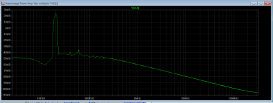
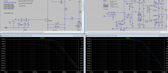
Still simulating the 2 pole miller compensation and now I am getting some strange results.... need some input.... THD seems quite similar but the base line is quite different.
I am comparing two very near resistors (5k and 5k1) with a 100k resistor that should act as an open circuit as if I am using only a single pole miller compensation.
Why does the graph begin at -100dB for the lower resistor and starts at -60dB with the open circuit ?
I am comparing two very near resistors (5k and 5k1) with a 100k resistor that should act as an open circuit as if I am using only a single pole miller compensation.
Why does the graph begin at -100dB for the lower resistor and starts at -60dB with the open circuit ?
Attachments
Still simulating the 2 pole miller compensation and now I am getting some strange results.... need some input.... THD seems quite similar but the base line is quite different.
I am comparing two very near resistors (5k and 5k1) with a 100k resistor that should act as an open circuit as if I am using only a single pole miller compensation.
Why does the graph begin at -100dB for the lower resistor and starts at -60dB with the open circuit ?
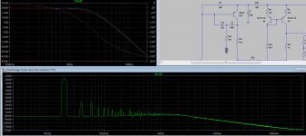
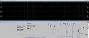
Show us an AC-analysis curve for both.
Hope this is what you need.... can not see any difference between using 5k or 100kr in this case.
PS: You might have a surprise tomorrow or the nest day... I am not sure you will receive it because swiss customs are very strict regarding exporting dangerous (mind altering) material without due clearance.
Please let me know 🙂
PS: You might have a surprise tomorrow or the nest day... I am not sure you will receive it because swiss customs are very strict regarding exporting dangerous (mind altering) material without due clearance.
Please let me know 🙂
Attachments
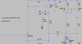
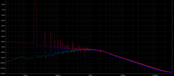
I do not see any significative difference between single and 2 pole miller compensation.
After rereading Self paper about it, I get the idea that this very small effect might be due to using CFP output stage.
As determining the second cap and resistor values is critical both to minimal distortion and also to stability (If not done correctly we might end up loading the vas collector directly to GND increasing nonlinearity), I finally decided to let the idea for future experiments and stick to the initial plan.
Now working on the layout..... post pics soon
Attachments
You should see the 2 poles in the GB-curve. Possibly the FT of one of the poles is selected so high that it is 'hidden' by the other 🙂
I do not see any significative difference between single and 2 pole miller compensation.
- Home
- Amplifiers
- Solid State
- Assemblage Power Amp