It was completed couple days ago and is under breaking in.
Albert - congratulations! Looks like you did a good job putting things together. You even got the JG buffer wired up point to point - good job. Let us know how you like it after you've had a chance to listen to it for a while. And remind everyone about any changes you made to the build from the BOM.
Thanks,
---Gary
Certainly a nice build but the heatsink on LM723 (and not on the output transistor) is intriguing ....
Maybe the picture is deceiving but try to keep the SPDIF wiring somewhat more away from the output signals.
You connected the case to PE, that is good. You also connected the audio GND directly to the case so to PE. In your DAC "PE = audio GND" ... There are some doubts regarding that. You will have a ground loop for sure if sources also have audio GND connected to PE.
Last edited:
Albert - congratulations! Looks like you did a good job putting things together. You even got the JG buffer wired up point to point - good job. Let us know how you like it after you've had a chance to listen to it for a while. And remind everyone about any changes you made to the build from the BOM.
Thanks,
---Gary
It is running and very quiet, no noise at all. Will certainly report after some serious listening.
Certainly a nice build but the heatsink on LM723 (and not on the output transistor) is intriguing ....
Maybe the picture is deceiving but try to keep the SPDIF wiring somewhat more away from the output signals.
You connected the case to PE, that is good. You also connected the audio GND directly to the case so to PE. In your DAC "PE = audio GND" ... There are some doubts regarding that. You will have a ground loop for sure if sources also have audio GND connected to PE.
Thanks for the heads up. Everything is good and quiet. Sounds good too.
As good as it gets?
I've been comparing the set up I described in post # 183 to my reference DAC. Just to recap, my current best sounding V3 DAC consists of:
--- V3 DAC with cap modifications described throughout this thread. C22 is a 470uf Nichicon FPCAP. C35 is a 4.7uf Wima MKS2. C4 is 3.3uf Wima MKS + 0.1uf MLCC.
--- V3 power supply upgraded to LT1764a with C-L-C pre-filter
--- JG buffer/filter with 150pf cap swapped to Wima FKP
--- PS for JG buffer is +-15v using TPS7A4700 regulator chip
My reference DAC for the last 2 years has been an ES9018 DAC based on the Twisted Pair Buffalo III kit. I use the latest shunt regulators from TP, outputs forced into current mode with low value resistors, transformer conversion from balanced to single ended, JFET buffer.
With the latest power supply changes and the addition of the JG buffer, I find that the V3 DAC is now sounding as good or perhaps a bit better than my ES9018 DAC. That is really a great accomplishment on two fronts. First the ES9023 project costs significantly less than the ES9018 project. Second, the ES9018 has embarrassed some very expensive DACs, so to meet this standard means it's playing in a very exclusive club.
My kudos to JP and Subbu for their efforts in bringing us this little DAC and their assistance in getting its sound up to this level.
All the best.
---Gary
It would be nice if you asked us first if we like our design being available in a copied/improved/changed version (better or not, is not relevant here). When you asked for it I sent the schematics to you as you wanted to do your own PCB design which is fine. You never stated the PCBs or the design would be available to others.
My apologies, I was going to double check before any real data was released, from our brief conversations and the fact that the data is covered under the creative commons attribution non-commercial share alike 3.0 unported licence (the same licence I release all my photos under). You had said you wish you has put the PSU on the same board, so once I did my simple version I started I started adding the PSU, then read that people were adding the JG buffer, so thought I would add that for fun. These things were done as I thought the DIY community could benefit from the work, and I did not believe I was breaking the above licence, and as said before a I released any data it would have been sent to yourself for approval/denial.
I got a bit carried away with the spirit of this site and as said thought it would be useful for others and a bit of positive contribution from myself.
On this note I will withdraw all data and have no further involvement.
Regards
Marc
Did you read my post right ? It is a simple direct post with direct statements or questions coming from a non native english speaker with a handicap for word play. No need for blah blah, preliminary conclusions and other noise. Also no need for apologies. Positive contributions are good and your knowledge and experience are well regarded. Getting carried away is one of the things that make this hobby fun so no hard feelings whatsoever.
Last edited:
My apologies were because I believe I have over stepped the mark (as we say), as you said I should have contacted you first, and I did not. I got caught up with the excitement (possibly not the correct word) and enthusiasm of this thread.
When I have finally finished all my versions of the circuit all data will be forwarded to yourself for further consideration.
Regards
Marc
When I have finally finished all my versions of the circuit all data will be forwarded to yourself for further consideration.
Regards
Marc
Thank you Marce for your links above. It's very interresting for improve the knowledge of fellows like me.
I believe it's compatible with the spirit of this thread :
1) The original version has already a great result with the BOM, and people can not do better without spending more or take risks (more money, loss of time, pcb break, own flavor way, ...).
2) This particular thread is for the fanatics, poets, hobbyst, Hobbits, assuming the risks, liking their hobby and taking fun with it.... each at their own level of skill and knowledge. blessed version has already its own thread.
J-P is sometimes rude because he has 1) in mind for the best interests of majority of diyers and he practiced 2) himself with Subbu to offer a more better version. (is it not V3 ? Yes it is). He maybe scares that people waste the 1) (I'm sure he doesn't scare than people like Garry can do better in the spirit of Demning wheel he practice himself). he remains a brave chap... (i use its vocabulary here)
I think this thread is respectull of this work and have already in mind 1) & 2)... Exchanges are positiv and big boys are free to waste, break or improve their toy. 2) substract nothing to 1) and the merits of the papas' designers.
You can sometimes see here rare people between the two approachs with judgement of valors about others who doesn't know themselves where they reside
 . stop the ego, it adds nothing.
My two cents and humble opinion, i like the idea than this post add nothing as people here are big boys but sometimes it's better when it is wrote. J-P and Marce, both your opinions are important as your knowledge is usefull for most of them.
I believe it's compatible with the spirit of this thread :
1) The original version has already a great result with the BOM, and people can not do better without spending more or take risks (more money, loss of time, pcb break, own flavor way, ...).
2) This particular thread is for the fanatics, poets, hobbyst, Hobbits, assuming the risks, liking their hobby and taking fun with it.... each at their own level of skill and knowledge. blessed version has already its own thread.
J-P is sometimes rude because he has 1) in mind for the best interests of majority of diyers and he practiced 2) himself with Subbu to offer a more better version. (is it not V3 ? Yes it is). He maybe scares that people waste the 1) (I'm sure he doesn't scare than people like Garry can do better in the spirit of Demning wheel he practice himself). he remains a brave chap... (i use its vocabulary here)
I think this thread is respectull of this work and have already in mind 1) & 2)... Exchanges are positiv and big boys are free to waste, break or improve their toy. 2) substract nothing to 1) and the merits of the papas' designers.
You can sometimes see here rare people between the two approachs with judgement of valors about others who doesn't know themselves where they reside
. stop the ego, it adds nothing.My two cents and humble opinion, i like the idea than this post add nothing as people here are big boys but sometimes it's better when it is wrote. J-P and Marce, both your opinions are important as your knowledge is usefull for most of them.
Hi everyone,
I just wanted to share my latest pictures of my favorite DAC.
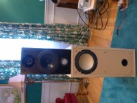
I included photo of my bi-amped speaker system just for your reference. top unit is stock Nola Mini. Bass unit is TiVi M8a bass reflex crossed at 350Hz.
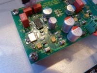
For C17, I have a 1uf X7R bypassed with 1nf. I hope you can see it. The 1nf is 0603. For C35 and C4 I use 1uf Wima. It seems the best set up for me. I think I've used every combination of mods on this thread. I think I ready to close the case. The PSU of course is the Salas BJT shunt. I think it is an improvement over the standard PSU. Bass has extra definition plus extra degree of smoothness with the Salas. Thanks everyone. 🙂
I just wanted to share my latest pictures of my favorite DAC.
I included photo of my bi-amped speaker system just for your reference. top unit is stock Nola Mini. Bass unit is TiVi M8a bass reflex crossed at 350Hz.
For C17, I have a 1uf X7R bypassed with 1nf. I hope you can see it. The 1nf is 0603. For C35 and C4 I use 1uf Wima. It seems the best set up for me. I think I've used every combination of mods on this thread. I think I ready to close the case. The PSU of course is the Salas BJT shunt. I think it is an improvement over the standard PSU. Bass has extra definition plus extra degree of smoothness with the Salas. Thanks everyone. 🙂
Attachments
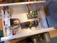

That is a beautiful build Freeman ! Exactly as I envisioned the placement of transformer and boards when the DAC board was designed. Since I like this build a lot I will mention some of the things that discern it from others:
1. Shortest possible connections.
2. Non ferro aluminum (aluminium) case.
3. PE connected to case, audio GND floating (uh oh, beware for comments!).
4. Solid mains switch.
5. Mains voltage connections safely insulated, something rarely seen in DIY gear.
6. Mains wiring far away from audio circuits.
7. Transformer far away from audio circuits.
8. I see you also use a mains filter. One question about that: did you listen to the DAC with and without the filter ?
9. SPDIF and L + R connector insulated from case.
10. PCB has been cleaned, no debri from flux.
I do notice some dry joints on the regs or am I mistaking ?!? I use physically smaller 10 µF caps but that is a tiny detail. I don't understand the double and twisted wiring but it sure looks good 😉
Thanks for showing,
regards,
Jean-Paul
Last edited:
That is a beautiful build Freeman ! Exactly as I envisioned the placement of transformer and boards when the DAC board was designed. Shortest possible connections. PE connected to case, audio GND floating (uh oh, beware for comments by electro fundamentalists!). Solid mains switch and mains voltage connections safely insulated, something rarely seen in DIY gear. I do notice some dry joints on the regs or am I mistaking ?!? I use physically smaller 10 µF caps but that is a tiny detail. I see you also use a mains filter. One question about that: did you listen to the DAC with and without the filter ?
Thanks for showing,
regards,
Jean-Paul
Thanks Jean-Paul,
I see the dry joints now too. I also tried the Subbu with and without my B1 preamp. There seems no difference. I haven't tried the JG buffer yet. Do you still prefer the Subbu without buffer?
Jean-Paul. I did listen with/without the filter. To my ears, it seems to provide an extra degree of cleanness to the sound. The mains power has reputation of being very noisy here in Tennessee. Regards.
Hi I never got hold of one. I also like my DIY stuff to be mounted nice, safe and aesthetically pleasing. Like you built your V3. Could not figure out to use the JG board in a neat way with our board. There was the option to design a "Subbu JG Buffer" PCB for the buffer combined with a symmetrical PSU roughly the same size as the DAC board but it did not materialize. The buffer design is not ours and it feels kind of awkward to get in the way of the people that designed and sold that design (even if they would have allowed that, who knows).
OK, good that the filter is an improvement. The original PSU has a common mode filter so with that one a mains filter won't improve matters as much.
Sorry folks, I could not resist. This a technically a very nice build and it can serve as an example of how to encase the V3. The mains wiring to the transformer could be a few cm further away from the low voltage secondary wiring but this is nitpicking. In true Spartan style there is not even a power LED, the "1" on the switch is all you need. Nothing that distracts from its function. No features but good sound. What else matters ?
Attachments

Last edited:
wowwww
It's very nice.... I'm jealous !
Are the big grey caps X2 ? Or just Vishays' ?
Well LF caps on C21 : I have to try with my next Subbu if you have already test all the hints here and find your mix curry better.
And enough place at C17 for something 10 or 100 nf more between your two values...Marce mode !
thanks for sharing.
Last edited:
wowwww
It's very nice.... I'm jealous !
Are the big grey caps X2 ? Or just Vishays' ?
Well LF caps on C21 : I have to try with my next Subbu if you have already test all the hints here and find your mix curry better.
And enough place at C17 for something 10 or 100 nf more between your two values...Marce mode !
thanks for sharing.
Hi Eldam! Thank you. The caps are here: https://www.mouser.com/Search/Produ...virtualkey64630000virtualkey80-R60DN5100AA30K
Hi everyone,
I just wanted to share my latest pictures of my favorite DAC.
At risk of repeating what others have said - wow! Your attention to detail puts the rest of us to shame. Glad to hear that your DAC is working well and that you like the sound. Welcome to the V3 club.
---Gary
Thanks Jean-Paul,
I see the dry joints now too. I also tried the Subbu with and without my B1 preamp. There seems no difference. I haven't tried the JG buffer yet. Do you still prefer the Subbu without buffer?
Since you may rework it, MOSFET output at 5V is feasible too as well as more CCS current hot-rod with your trafo and low TO-220 temperatures. Flavors to pick from.
Well done, Freeman.🙂
Thanks for the kudos guys. I feel like I just won an Oscar or something...so I'll make a speech. I'd like to thank Subbu, Jean-Paul, Gary, Eldam, Fred, Salas, Marce, and everybody else for making this build possible. Thanks for all you do.

- Home
- Vendor's Bazaar
- Modifying the Subbu V3 DAC