Forgot to mention in my last post. Some of you asked the dimensions of the makeshift speaker. I slapped that together from four 12" lengths of 8" wide flooring. So its 12" x 12" x 8". The woofer is on the bottom with the tweeter right above it. It has a 4" x 2" port. To me, the bass from this one is thunderous and powerful.
Too many cooks! The job of the port is (at least mostly) to extend the bass response, not boost it. The losses from blocking the 5" port would be mostly below ~60Hz, and thus might not be very noticeable when playing random music, especially if you happen to have a room null around there. Shorten the port to 18mm or whatever, and now you're blocking/unblocking a big bass peak - much more obvious.
In this cook's opinion, just shorten the port to ~3.5", wire up a proper crossover design, and see what you get.
In this cook's opinion, just shorten the port to ~3.5", wire up a proper crossover design, and see what you get.
Forgot to mention in my last post. Some of you asked the dimensions of the makeshift speaker. I slapped that together from four 12" lengths of 8" wide flooring. So its 12" x 12" x 8". The woofer is on the bottom with the tweeter right above it. It has a 4" x 2" port. To me, the bass from this one is thunderous and powerful.
Great, that's helpful. So that's approximately 16L, tuned to 51Hz which will give you the blue curve in the graph below and that was giving you about a 6dB boost between 60 and 70Hz (baffle step loss is not included since I figured you probably had it on your test bench or something so the bass was getting boundary reinforcement which negates at least some of that loss).
Violet curve is from your plywood cab with the 2" x 5.75" port again and with the 6dB baffle step loss. So you should have heard a pretty big difference between those 2.
I'm with dumptruck here - to make valid evaluations of the box alignments, you're going to need the xo in place. I'm sorry I didn't think of that earlier. And I'll go a step further and say you should also put your internal stuffing in place so that the cab (and response) will be as close to the finished product as possible because the stuffing will change the response as well.
Once you get it in place, then you'll be in a better position to judge exactly what kind of response you like best for your ears and in your room.
Attachments
I'm with dumptruck here - to make valid evaluations of the box alignments, you're going to need the xo in place. I'm sorry I didn't think of that earlier. And I'll go a step further and say you should also put your internal stuffing in place so that the cab (and response) will be as close to the finished product as possible because the stuffing will change the response as well.
Once you get it in place, then you'll be in a better position to judge exactly what kind of response you like best for your ears and in your room.
Nothing to be sorry about. I know I'm doing things out of order but I'm trying to learn as I go.
I'm going to order the right crossover parts you showed in post 32 (plus the extra parts shown in post 33). Before I do I have a couple of questions. On the HP does that end up being a xo freq of around 3.5K? Next is there such a thing as a 6uf cap? If not is 6.8 or 5.6 OK? I dont know anything about stuffing. Which one should I get and how much?
Thanks
In this cook's opinion, just shorten the port to ~3.5", wire up a proper crossover design, and see what you get.
Ok cook. Is 3.5 my ideal length?
I think you got those post numbers wrong? Order a lot of extra resistors. I don't know what your ideal port length is, just recommending a little shorter to compensate for some enclosure losses. I think it's pretty well-established with this woofer that you want around 1.3-0.3 ft³, tuned somewhere in the Fs neighborhood, where smaller enclosures give a less-extended response with a little extra bass and higher power handling, larger gives deep extension and lower power handling. Either end of things should be able to give a subjective "plenty" of bass, really.
Last edited:
Yes too many cooks basically saying exactly the same thing more or less. 🙂
From modeling this driver and the input from others, it can be used well within a range of box sizes that'll affect Q, Fc and adjust port length to compensate. Even the port size / length being of similar tuning.
It's not like if we were off by a tenth the whole pie falls apart 😉
From modeling this driver and the input from others, it can be used well within a range of box sizes that'll affect Q, Fc and adjust port length to compensate. Even the port size / length being of similar tuning.
It's not like if we were off by a tenth the whole pie falls apart 😉
Tony,
I just ran this driver through BassBox 6 Pro which has both the published specs for this driver (295-335) and a set of measured specs. Standard Bass reflex alignment with a 2" diameter port, normal dampening, golden rule enclosure.
The published specs give me a box size of 0.7'³, with an F3 of 36.5Hz.
The measured driver give me a box size of 0.78'³, with an F3 of 35.Hz.
In both cases driver would be over driven below cutoff with more than 25 watts so a high pass would be a safe bet.
If you want I can email you the full results.
I'll PM you on that and also about what I got hanging from the ceiling.
I think you got those post numbers wrong? Order a lot of extra resistors. I don't know what your ideal port length is, just recommending a little shorter to compensate for some enclosure losses. I think it's pretty well-established with this woofer that you want around 1.3-0.3 ft³, tuned somewhere in the Fs neighborhood, where smaller enclosures give a less-extended response with a little extra bass and higher power handling, larger gives deep extension and lower power handling. Either end of things should be able to give a subjective "plenty" of bass, really.
See. I cant do anything right. It was posts 27 and 28.
Thanks
I think I better abort this project while I'm ahead. Using parts on hand (the same ones from the makeshift speaker) I connected a crossover to the speaker. I even fooled around adding inductors in series or caps in parallel. I got this as close as possible to jReaves simpler crossover. Still no bass with the speaker standing up. This is no offense to jReaves . There is simply something wrong with my ears or my room or somewhere that nothing in a crossover can correct.
I'm not stupid, and nobody here has suggested that I am (I'm sure some of you have thought it 😉) After what I'm about to say you will all think I'm stupid and give up on me and I don't blame you, but its pure logic.
If I took a twelve inch woofer, paralleled it with a screaming 110 db midrange and then paralleled that with a screaming 110 db tweeter - all done with no inductors or caps at all - no xo at all in the system, it would sound horrible but the fundamental bass would still be there. You would still sense, hear and feel it at low volume if standing near the speaker, and at high volume, whether you were near the speaker or not, the walls would shake or something in your room would resonate. You cant erase bass if its there no matter how much you boost mids or highs.
My speaker, standing upright, just sounds flat and boring and has no depth or punch to it. There are forces at work here that are eating up my bass that no xo will solve or its my tin can ears. Laying the speaker down is a whole different world.
Tony
To really prove how crazy and off the wall I am this is a cat toy. If the cat touches it, it squeaks and lights up blue and blinks. If I crank up my speaker laying down, with the toy 20 ft away, the toy gets triggered. With the speaker standing up nothing happens. The "makesshift " spekaer triggers it with ease. The Overnight Sensation MTM triggers it easily as well.
They're coming to take me away, ho-ho, hee-hee, ha-haaa.
To the funny farm, where life is beautiful all the time and I'll be happy
to see those nice young men in their clean white coats and they're coming
to take me away, ha-haaa!!!
They're coming to take me away, ho-ho, hee-hee, ha-haaa.
To the funny farm, where life is beautiful all the time and I'll be happy
to see those nice young men in their clean white coats and they're coming
to take me away, ha-haaa!!!
Attachments

I'm going to order the right crossover parts. Before I do I have a couple of questions. On the HP does that end up being a xo freq of around 3.5K? Next is there such a thing as a 6uf cap? If not is 6.8 or 5.6 OK? I dont know anything about stuffing. Which one should I get and how much?
Thanks
And I had checked the values against what's available too..... oh well. Let's go with 6.8uF. It works better (see below)
Given how it's becoming apparent that the bass is important to you, I just went over the xo a bit, simplified it and changed the baffle step compensation from 4dB to 6dB by increasing the woofer inductor just a touch and dropping the tweeter level a little more. The response ends up a little flatter although the driver phase in the xo region isn't quite as well aligned as before but I think it's a good compromise. So I'll re-post all the info to be clear.
First is the parts. All the caps could be non polarized although the tweeter cap of 6.8uF benefits from being higher quality. The bigger inductor can be iron cored while the other 2 can be 20 gauge air core. It's good advice to get extra resistors because these are values that can be changed to suit your tastes. So maybe get 1 x 5ohm value and then a bunch of 1 0hm values that can be added and subtracted in series and parallel to get to the values you want.
The LCR notch filter circuit on the woofer after the xo is the optional one. You may or may not notice the difference. I can't say for sure. Here the resistors and the cap could be modified to see what works best, so same as above for the resistor (5ohm +++ 1 ohm) and you could get a 50uF plus 2 x 10uF to try 50, 60 and 70uF if you want, although I think it'll work nicely as is (ie at 60uF). I had an optional LR circuit on the tweeter last time around but by changing R1 from 4ohm to 6ohm the rising response on it seems to be sufficiently taken care of that you don't need it any more.
For this sim, I used the bass response from 28L tuned to 45Hz with the walls covered with insulation so you can see how that looks. Doesn't affect the xo. There are many types of insulation that you can use. Heavy felt if you can find it. Some kind of open cell foam if that's easier. Thin 1" or 1.5" memory foam mattress toppers work well and they're easily found at Wallmart in my neck of the woods. About $40 for a twin, I think.
Did I cover everything or miss something again? Oh yes, the cross over frequency is where the blue and red curves intersect - about 2600Hz. The way that the response of the DA175 falls off above 1000Hz won't let it be crossed as high as 3500Hz.
Cheers
Attachments

There are forces at work here that are eating up my bass that no xo will solve
I guess the mounting of the removeable baffle is not really air-tight and that's eating up the bass. Did you use sealing strips?
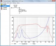
The upper impedance peak of the woofer should be at 50 Hz in your current setup, but you measured 70 Hz, that's an indication something is wrong indeed.
Attached a simulation of the Dayton in your cabinet (volume 1.3 cu ft, port 2" x 5.75").
Attachments
Phoenix,
has your owner started his New Year's Eve celebrations a little early??!!
Yeah that's part of the problem. Speakers are driving me to drinking and I thought a little humor was needed here.
Anyway I just ordered all the xo parts. I took down the xmas tree and was able to put the speaker (standing up) in the corner. Huge difference. More than enough bass now.
The only oddity that remains is that no matter what length port I put on there the low bass fades out. It seems to like just the opening hole best.
Tony
Last edited:
I guess the mounting of the removeable baffle is not really air-tight and that's eating up the bass. Did you use sealing strips?
The upper impedance peak of the woofer should be at 50 Hz in your current setup, but you measured 70 Hz, that's an indication something is wrong indeed.
Attached a simulation of the Dayton in your cabinet (volume 1.3 cu ft, port 2" x 5.75").
Thanks for that simulation. You are probably right. If you read my last post I'm finding something is very wrong with the port. The cabinet is sealed everywhere but the baffle is in fact just screwed on.
Before I play around with sealing it I was wondering if someone could explain the two impedance peaks and why they occur. Being something that I have the equipment to measure, it would be beneficial and productive to understand it.
Every driver has an impedance peak at its natural resonance, Fs, in free space.
When you put it in a sealed box the peak moves to the resonance of the box, Fb, and its shape will change depending on the size of the box - narrower in a smaller box and wider in a larger box.
When you put it in a vented box you get 2 impedance peaks this time with the minimum between them at the box resonance, Fb. Or conceptualized another way, you again get 1 large impedance peak that is split in 2 (not necessarily in half) by the null at Fb. So in the same way that the cone has very little travel at Fb, so too does the vented box impedance peak have a null in the same place. Interestingly, the shape of this (larger) impedance peak operates in the opposite manner than the sealed one - in a small box it's wider (so the 2 smaller peaks are wider apart) and in a large box it's more narrow (2 peaks closer together) . (Don't ask me to explain why, I haven't got a clue)
Now as to the effects of leakage on impedance, you're going to have to ask Dissi that. I noticed the difference in your 2nd impedance peak too but I didn't know what it meant. Dissi?
As far as making your cab air tight, many people use thin weather strippping or some other thin closed cell foam as a gasket for a removable baffle. But that removable panel needs to be air tight as well.
As a learning tool btw, I have found Unibox to be an invaluable tool. I think it does a few more things than WinSD does but I also find its user interface much easier to use and to learn from. Play around with that for a few hours and all kinds of cause and effect relationships start to become very apparent. It needs Excel though.
UniBox - Unified Box Model for Loudspeaker Design
Oh - enjoyed the humor. Hope your head is feeling fine today. 😉
When you put it in a vented box you get 2 impedance peaks this time with the minimum between them at the box resonance, Fb. Or conceptualized another way, you again get 1 large impedance peak that is split in 2 (not necessarily in half) by the null at Fb. So in the same way that the cone has very little travel at Fb, so too does the vented box impedance peak have a null in the same place. Interestingly, the shape of this (larger) impedance peak operates in the opposite manner than the sealed one - in a small box it's wider (so the 2 smaller peaks are wider apart) and in a large box it's more narrow (2 peaks closer together) . (Don't ask me to explain why, I haven't got a clue)
Now as to the effects of leakage on impedance, you're going to have to ask Dissi that. I noticed the difference in your 2nd impedance peak too but I didn't know what it meant. Dissi?
😉
Oh so the minimum occurs at the Fb. I had it wrong in my head. I was thinking the first peak was the Fb and that maybe the second peak had something to do with the Fs being shifted higher due to being in the box and not in free air..
You mean there is actually something you don't have a clue about regarding speakers. Say it isn't so.🙄
- Status
- Not open for further replies.
- Home
- Loudspeakers
- Multi-Way
- First Build Dayton DA175 and Vifa BC25SC06-04