Your welcome,Thank JOHN BALI, buz900d/901d is another option for those who want to-3, I'll ride with 2sk/2sj.
now you should pick one, Shaan version, PMI version, or John Bali version 🙂
If you like my last one & untested I'll give you the file 😀.
I guess I will try it myself soon
& we are waiting for your build.
Regards
The Alfets are available in TO-3. They are more expensive, but if one wants to build a complete amplifier with a transformer, power supply, chassis, etc, the incremental cost of an expensive transistor is not so bad.He, he, did you get good look at those MOSFETs? Those came from an old Soundcraftsmen ...
Having said that, I am definitely in favor of recycling old gear... 😀
The Alfets are available in TO-3. They are more expensive, but if one wants to build a complete amplifier with a transformer, power supply, chassis, etc, the incremental cost of an expensive transistor is not so bad.
Having said that, I am definitely in favor of recycling old gear... 😀
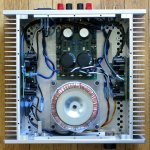
I was just tickled they worked. I tried and tried to get that poor old Soundcraftsmen working but it was just too beat up. I was able to salvage the 4 pair of outputs and the transformer. That transformer is a 70-0-70vac beast. Not sure what I can ever use that for. With my home voltage at around 122vac that sucker puts out +/-100vdc.
Blessings, Terry
It's a win, either way you look at it. A typical transformer today has a dual primary designed to be wired in parallel for 115 and in series for 220. So: wired in series, like the 220 connection, the secondary voltage will be 35-0-35, with the VA rating reduced, but still usable... 😀I was just tickled they worked. I tried and tried to get that poor old Soundcraftsmen working but it was just too beat up. I was able to salvage the 4 pair of outputs and the transformer. That transformer is a 70-0-70vac beast. Not sure what I can ever use that for. With my home voltage at around 122vac that sucker puts out +/-100vdc.
Blessings, Terry
(I am using a couple like that for testing, and they work just fine, they just don't look very presentable... )
I've had some questions about comparing the different circuit board versions, which is frankly difficult. They all sound very good to my ears, including the simplest version I built which is essentially identical to Shaan's original circuit. Each is a little different, but it takes careful listening, and very good speakers to hear the differences.
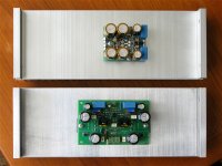
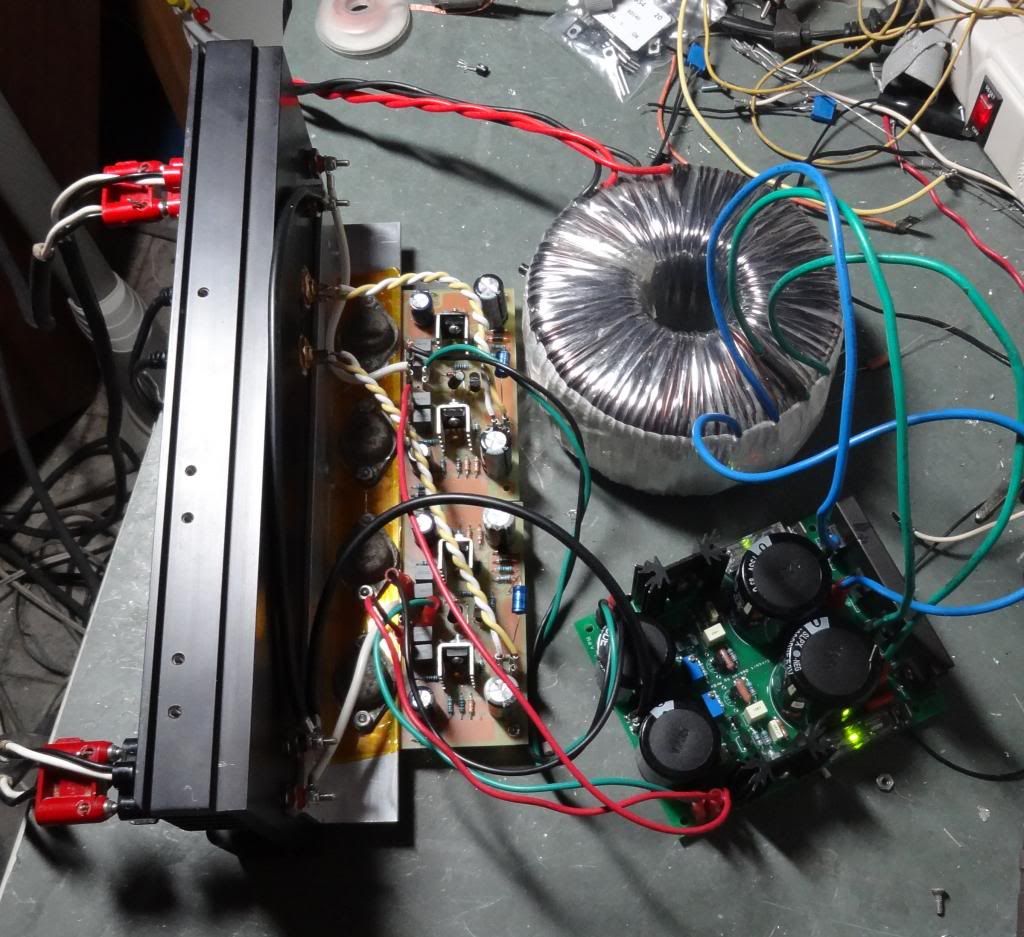
You can't beat the compact layout of Lazy Cat's module with SMD components on both sides, and the dual Alfet. (See side-by-side pics below)
My goal was to make a layout which could be built easily, with all through-hole components, and with conventional power transistors like the Renesas parts or the Alfets, and with parts that could all be ordered easily from online distributors. Not to make the smallest board possible.
I hope to have the first manufactured board in my hands by middle of next week, so there are no pics of the new one yet, but the layout of the key components is almost identical to the first version which is shown below.
Test results have been posted in several installments earlier, starting at Post 335.
Attachments
Post 335.[/URL]
Where do you buy the outputs?
I bought the Renesas parts from Tayda Electronics. Recommendation someplace here on diyaudio. They shipped much faster than I expected, and those are the parts I have been using for testing.Where do you buy the outputs?
Newark and Allied Electronics both list the Semelab Alfets in their catalog, but the availability is limited, depending on which one you want, and Newark adds $20 to every order if stocked in the UK. Other than that, the price is not so bad, when you consider that Renesas probably sells 100 times as many.
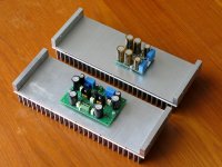
I mounted the boards on a heatsink. It is just ample. The heatsink is running at 40C. The outputs themselves are right at 44C. I can leave a finger right on them indefinitely. What I do think is too hot are the VAS, Those are 55C. Can't leave my finger on them at all. Is there a way to lower the current on those? Maybe I just need to put larger sink on them. I have had it playing all day on 4 ohms. It sounds really nice.
Blessings, Terry
Blessings, Terry


Terry,
The VAS transistors do run fairly warm on these and you are running on the upper end of the recommended supply voltage range. If you can get a voltage measurement across one of the 10 ohm resistors in the one of the VAS transistor emitter circuits you can calculate the VAS current. It should ideally be about 12mA, so to the tune of 120mV across R12 or R16 on the schematic I supplied. These are the 10 ohm resistors found between the electrolytic capacitors on those boards.
If the bias is too high replace the 18k resistors with 20k and recheck. The VAS devices I sent you are pretty hardy and are likely OK as they are. Oh, one other thought, did you use some heat sink compound on them? I don't see the usual signs of thermal paste in the pics.
Any specific thoughts on the sound? I'm very curious as to how these stack up sonically to some of the other projects you have built. As I have mentioned they are my personal favourite.
Last edited:
Nice pics Terry!...What I do think is too hot are the VAS, Those are 55C. Can't leave my finger on them at all. Is there a way to lower the current on those? ...
If the heatsinks are too hot to leave a finger on them, you should probably lower the current a bit. Shaan, and later Ivan Lukic posted about that.
I would measure the voltage across the 10R which is at the VAS, and estimate the current first. Then decide if, and by how much you want to lower it.
The resistor which is listed as 15K in the original schematic can be adjusted (increased).
Usually that is done to put the VAS current in the proper range at higher supply voltage ranges. I believe that Shaan originally used the 15K at something like +/-25V supply. There have been a few posts on what values correspond to different supply voltages.
Having said that, some of the VAS transistors were originally made for hi-res CRTs, and they were designed to work at higher temps than you might expect in audio.
edit:
Or, just do as Jason said above... I've never been a very fast typist (chuckle)
Last edited:
@PMI
In anticipation of the higher rails I knew Terry would be using I specified 18k for the 'current injector' resistors. He may have to go to 20k or even 22k if the bias is genuinely too high.
Hopefully he can get a measurement of the VAS current via the voltage across one of the 10 ohm resistors.
In anticipation of the higher rails I knew Terry would be using I specified 18k for the 'current injector' resistors. He may have to go to 20k or even 22k if the bias is genuinely too high.
Hopefully he can get a measurement of the VAS current via the voltage across one of the 10 ohm resistors.
With your boards and the correct component values, this should work safely up to about 50V, right? (assuming ~8 ohm loads)@PMI
In anticipation of the higher rails I knew Terry would be using I specified 18k for the 'current injector' resistors. He may have to go to 20k or even 22k if the bias is genuinely too high.
Hopefully he can get a measurement of the VAS current via the voltage across one of the 10 ohm resistors.
I would think with my component choices they could. Obviously some resistor values would need to be tweaked when pushing the voltages higher. The outputs and VAS are 160V devices and the input transistors are 120V parts so the semis are good at the 50V level.
Just caught your edit, yes over 40V would be limited to 8 ohm. Unless you got some shiny double die BUZ or ALFET parts 😀.
Just caught your edit, yes over 40V would be limited to 8 ohm. Unless you got some shiny double die BUZ or ALFET parts 😀.
Last edited:
OK I just measured the 10R resistors and they are 200mv so it looks like I need to change out those 18K. I will do that in the morning and try it again. I'll let yo know how it goes. May need to go even higher than 20K.
Blessings, Terry
Blessings, Terry
Which input transistors did you specify?I would think with my component choices they could. Obviously some resistor values would need to be tweaked when pushing the voltages higher. The outputs and VAS are 160V devices and the input transistors are 120V parts so the semis are good at the 50V level.
Just caught your edit, yes over 40V would be limited to 8 ohm. Unless you got some shiny double die BUZ or ALFET parts 😀.
Yes, I plan to try some double-die Alfets, eventually, unless someone else beats me to it. I've never used a part like that, and I like the idea of having devices that are matched at the factory. First I need to test with the same parts I used last time though, to get a baseline. My boards should be here later this week.
OK I just measured the 10R resistors and they are 200mv so it looks like I need to change out those 18K. I will do that in the morning and try it again. I'll let yo know how it goes. May need to go even higher than 20K.
Blessings, Terry
You may have to go back through the DC offset adjustment procedure as well after making the swap. Just give it a quick check after changing the resistors, total of four pieces, two per board. You likely won't have to go too high. Try 20k first and then 22k if needed.
Good luck, kindly post back your results.
20 mA is high, but not terribly excessive. What is the supply voltage?OK I just measured the 10R resistors and they are 200mv so it looks like I need to change out those 18K. I will do that in the morning and try it again. I'll let yo know how it goes. May need to go even higher than 20K.
Blessings, Terry
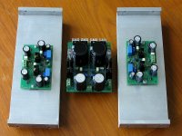
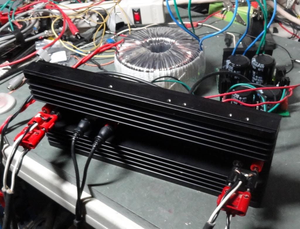
By the looks of those heatsinks, they are about the same size as some 25C/W heatsinks I have from Aavid-Thermalloy/Mouser.
So, my point is that at say 40V and 20 mA, the heatsink should not be too hot to touch.
@Jason, am I missing something here?
Which input transistors did you specify?
Yes, I plan to try some double-die Alfets, eventually, unless someone else beats me to it. I've never used a part like that, and I like the idea of having devices that are matched at the factory. First I need to test with the same parts I used last time though, to get a baseline. My boards should be here later this week.
I sent out some KSA992F and KSC1845F for the inputs and KSA1220A and KSC2690A for the VAS. Bought a ton and has no issue ensuring Terry got some good components for the build.
20 mA is high, but not terribly excessive. What is the supply voltage?
By the looks of those heatsinks, they are about the same size as some 25C/W heatsinks I have from Aavid-Thermalloy/Mouser.
So, my point is that at say 40V and 20 mA, the heatsink should not be too hot to touch.
@Jason, am I missing something here?
In my opinion, 20mA would run the VAS too hard with the type of sinks I supplied. At that level they would need more significant cooling. If brought down to the more usual 12mA the supplied sinks will be fine.
If I recall correctly he has the cap multiplier set to output about 37V. I'm thinking the swap of resistors will do the trick. Hopefully we hear good news from Terry sometime tomorrow.
I will check that as well. Earlier today I changed the size of the angle I had the outputs mounted to and I didn't mark them when I took it apart so I must have swapped them when I reinstalled because the DC offset was different. I just hooked some jumpers to either side of one of the 18K resistors and then tried different resistors until the offset was gone. I think I needed 1k5 on one of them and 2k3 on the other. First time around one didn't need anything and the other only need 1k. Simple enough to do.
Blessings, Terry
Blessings, Terry
- Home
- Amplifiers
- Solid State
- PeeCeeBee