Or use black anodized plate on the front and then engrave the design out (so there is a deep enough groove) and add in white paint.
I don't think you should flip the diagram on its side, nor use the concentric arcs at input and output (see the sine wave NP uses to indicate larger signal), nor use some non-standard potentiometer-looking connection (with the arrow) to the V rails. Keep it as standard as possible...
+1, the concentric arcs look like a sign of an antenna, sine waves will look nicer...
I have F3's and really like them. I've been wanting to build the F4 for sometime and in anticipation I built the Impasse preamp. The transformer group buy pushed me over the top. I had heatsinks and power supply boards from previous group buys. When they are all together I can get a good AB comparison.
Just speaking because I can, I kind of like that anodized black front plate.
If you really wanted to get kind of in your face about it (well, too late for that since the etched circuit diagram is staring you in the face already), then put a diode symbol in the circuit diagram for the power indicator, and drill a small hole corresponding to that and put in a diode.
But for mercy's sake, use a relatively conservatively rated light output diode (your amp, your colour choice, but I am partial to the orange or green ones). I was victim to an amp last week and I so wanted to turn off the amp as the light from was so agonizing (remember at the end of Indiana Jones when they open up the ark? That amp used it as inspiration).
Since I am full of opinions when projects aren't my own, I would make a slight design recommendation to the face plate -- make it overhang the edges top, bottom, and sides by 2 or 3 mm than the side fins, bottom plate, and top plate.
Furthermore, make the diagram maybe 92.5 - 95% of what you have it on the current face plate mock up. It seems to be too close to the top edge.
Otherwise, it is very sweet looking.
evanc,
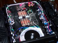
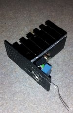
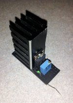
I have the parts for the speed controller but also a question. Does the thermistor need to be in contact with the heat sink or Mosfet? I can't find it in your photos.
I have the parts for the speed controller but also a question. Does the thermistor need to be in contact with the heat sink or Mosfet? I can't find it in your photos.
Attachments
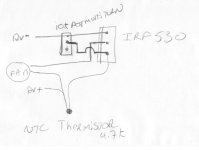
The Thermistor is monitoring the cooling requirements of the amplifier.
Not, I suspect, detecting overheating of the motor.
Not, I suspect, detecting overheating of the motor.
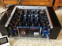
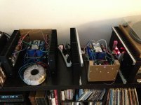
I have the thermistor touching the heatsink. You can see it in the third photo...brown and white wire.
Last edited:

12B4A, 
What he said 😀You should still have the supplies shown, but in general it looks good!
You should still have the supplies shown, but in general it looks good!
I know I should. I'm just trying to come up with a way that doesn't make it look like a shirt with a price tag hanging off it.
V+ and V- are bad? Or just + and - ?
I liked the line with the bump that was in the first drawing. But I like the + and - better.
Regardless, you will come up with something good, I'm sure.
I liked the line with the bump that was in the first drawing. But I like the + and - better.
Regardless, you will come up with something good, I'm sure.
Here's another attempt using the simplified diagram. It looks a bit better IMO.
I am partial to the complex diagram because it a perfect representation of what is inside the box and it just looks cool.
- Home
- Amplifiers
- Pass Labs
- Pictures of your diy Pass amplifier