Does 1.5° @ 20kHz matter?
That equivalent to 0.21us (maybe?)
If I would know it doesn't matter - would I ask for? 😉
Have seen somewhere High End Audio datasheets where marketing praises phase shift < 1.5° @ 20kHz as supa dupa special feature.
And if your and my calculation is correct then we talk about 60µm distance.😀
BR, Toni
By the way, I think that well implemeted TMC will chalenge pure Cherry, but without stability problems.
Well that is the challenge I've issued in my tpc-vs-tmc-vs-pure-cherry thread. 😀Each of these implementations have their benefits but I like TMC the most as it targets the output stage distortion which is exactly where its needed the most.
So far the challengers have not been very good but next week I hope to look at Damir's designs. They appear to be the best yet. 🙂
Manso, 'pure Cherry' takes this philosophy to the extreme.
Thanks for these Toni. I've updated my .ASC files and include them here.attached current amp using new drivers and with your cherry compensation changes. A quick check of loop gain shows we have less 30 degree phase margin and less as 10dB gain margin with new drivers. Would you please be so kind and try to adapt your cherry recommendations to this version?
2stageef_class_ab_power_amplifier_cherry.zip
ricardo.txt can be replaced with Cordells-Models.txt
The Model is set up to run THD as it stands.
Uncomment the '; THD' block and comment out '; LOOP GAIN ANALYSIS' block.
Instructions are in Analyzer_Controls.txt
When you get
* "Plot .step'ed .meas data" command.
* Right mouse button click on opened plot
Plot Settings
Open Plot Settings File
select THD.plt
To see the 20kHz residual, look at V(notch) between 0.5ms & 0.6ms
A quick stability analysis suggests for these new transistors, the cap. across the VAS emitter resistor should be 220p and there is no need for a series 10R resistor. I won't be able to do a full analysis until end of next week.
Attachments
My question is, when is two pairs of outputs not enough for one person?
One of my targets always is to have minimum 15w class A power. With optimal biasing output bjt's, you need at least 6 pairs. (Dependant on the emitter resistors offcourse)
8 pairs are needed serving full power to 3R without violating the SOA.
The resulting bias current of about ~ 400mA using 0.47R emitter gives you a comfortable Class A region for small signal listening.
BR, Toni
The resulting bias current of about ~ 400mA using 0.47R emitter gives you a comfortable Class A region for small signal listening.
BR, Toni
...
A quick stability analysis suggests for these new transistors, the cap. across the VAS emitter resistor should be 220p and there is no need for a series 10R resistor. I won't be able to do a full analysis until end of next week.
Dear kgrlee,
thank you for update. No problem to wait some days for the simulation results. Will do a real world test with those "quick test" values.
BR, Toni
My question is, when is two pairs of outputs not enough for one person?
... if you want to do bi-amping with active crossovers ... 😉
 😀
😀One of my targets always is to have minimum 15w class A power. With optimal biasing output bjt's, you need at least 6 pairs. (Dependant on the emitter resistors offcourse)
For an 6R load, this means 600mARMS. For 6 pairs that means 100mA each.
This is smart as it takes the approach of "not distorting in the first place". Appeasing the 27mV/octave curve of BJTs in this way ends us up with gratuitous SOA and few high order harmonics in the first watt zone. We may choose to use smaller, faster devices in the spirit of parallelism and although total parasitic C will be larger, combined Ft will be faster, increasing potential for the frontend. The devices must be spread out over a large area so local parasitics may be more difficult to manage.
The problem is, AFAIK there is a gap for power BJTs which have suitable Pd*Ft factor that are linear to 1A or more. I like the C4883A/A1859A, for which you will find models in my file a few pages back, but they are difficult to get.
The reason TPC doesn't have 20KHz phase shift like TMC/Cherry is because it does not capacitively load the IPS (and therefore emulate a LP filter). TMC/Cherry do, but with a benign signal derived from the undistorted output. If you count phase distortion, this may be a win for TPC. TPC still emulates a LP filter, but a quirky one at much higher frequency, so less audio-band error.
I think you got the arithmetic mixed up.For an 6R load, this means 600mARMS. For 6 pairs that means 100mA each.........
15.5Vpk into 8r0 gives a current of 1.9375Apk.
That is equivalent to 15.01W into 8ohms.
For Push-Pull ClassA the output bias must be set to >1.9375/2, i.e. >0.969A
A 5pair using Rs=0r1 will give that bias and Vre~19.4mV. This may be slightly more than optimal ClassAB bias.
If the full 15W of ClassA is important (for advertising !) then 6pair with Vre=18.5mV & Re=0r1 would allow the bias current to exceed that 0.969A requirement.
As an aside 15W of ClassA would be 10dB below maximum power of 150W into 8r0 if the 6pair devices were rated ~70 to 80W, To220 would do this, or lower power & cheaper To3p.
Thanks for these Toni. I've updated my .ASC files and include them here.
...
Dear kgrlee,
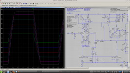
simulation shows some instability running square wave signal tests - see attached picture.
Have tested these values also in real world. First it looked good on doing sinus tests. Have seen some oscillation during tests and tried afterwards square wave signal test.
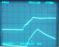
On increasing the 10kHz square wave signal the amplifier starts to oscillate on rising edge (see attached picture 2).
Maybe you have an idea ...
BR, Toni
Attachments
8 pairs are needed serving full power to 3R without violating the SOA.
The resulting bias current of about ~ 400mA using 0.47R emitter gives you a comfortable Class A region for small signal listening.
BR, Toni
And each new pair introduce 500pF non linear capacitance to Your amplifier...
Sajti
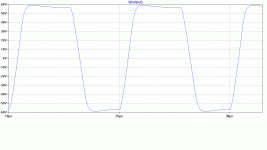
Toni, I've modified my model to try & match the one you show in post #233. I'm not sure about the relevance of full power 100kHz square waves but I get a different shape from what you show.simulation shows some instability running square wave signal tests - see attached picture.
Have tested these values also in real world. First it looked good on doing sinus tests. Have seen some oscillation during tests and tried afterwards square wave signal test.
On increasing the 10kHz square wave signal the amplifier starts to oscillate on rising edge (see attached picture 2).
Maybe you have an idea ...
I'd like to get my model to match yours before doing any more serious work on this.
I've included my .ASC file. Can you post the one you used in #233?
Attachments
I replaced your evil C3/4 0u1 but are you really taking Q9, the VAS enhancer's collector to clean GND?Toni, I've modified my model to try & match the one you show in post #233.
It has substantial current especially on overload which has to flow through your R76 10 making your clean GND go up & down wrt the output. 😱
Toni, I've modified my model to try & match the one you show in post #233. I'm not sure about the relevance of full power 100kHz square waves but I get a different shape from what you show.
I'd like to get my model to match yours before doing any more serious work on this.
I've included my .ASC file. Can you post the one you used in #233?
Maybe you have rise/fall time set to zero which smoothes your square wave. LTSpice seems to not accept zero here and replaces rise time by a programming default. I always set rise/fall time to 1n and 10n to see what happens.
V3 Vein 0 PULSE({-Vinp} {Vinp} {delaytime} 1n 1n {ton} {tperiod} {cycles})
Attached my asc file.
BR, Toni
Attachments
I replaced your evil C3/4 0u1 but are you really taking Q9, the VAS enhancer's collector to clean GND?
It has substantial current especially on overload which has to flow through your R76 10 making your clean GND go up & down wrt the output. 😱
Your are right. Affects testing and simulation like:
THD20k@200W@8R:
Collector Q6 to CleanGND = 0.000671%
Collector Q6 to PowerGND = 0.000668%
For real life and testing R76/10R is here to break internal ground loop as power ground gets a connection to star ground and input gets also a connection to star ground. For better and correct simulations we should set R76 to 0.010R.
BR, Toni
Think of current loops. Q6 collector is a potentially high DI/Dt spot so loop area from collector to emitter load should be small. It should travel through as few decoupling caps as possible. Decoupling it to the rail at the VAS will minimize one loop. The other loop is through the VAS Cob.
Note that the VAS is on the same rail as the positive drivers, but not the negative drivers. Thus the VAS current for the negative drivers travels in a larger loop and through two sets of decoupling. This loop can be shorted by placing decoupling across the rails at the driver collectors.
This is all stuff to keep in mind and to try, to see if there is an effect, although it may do nothing. Note that introducing high-Q decoupling just anywhere will create troublesome resonances, so it is helpful to have some tiny lossy lytics on the rails (.2R-1R) for effective dampening.
- Home
- Amplifiers
- Solid State
- 2stageEF high performance class AB power amp / 200W8R / 400W4R