Thanks Ian,
Schematic helped to identify bad solder on one of the ufl connectors. all fine now with dual Buf3.
next step is to synch the dual dacs. Anyone have any tips on how to desolder the clocks on the buf3?
regards
Schematic helped to identify bad solder on one of the ufl connectors. all fine now with dual Buf3.
next step is to synch the dual dacs. Anyone have any tips on how to desolder the clocks on the buf3?
regards
I'd be interested in the SPDIF board drill pattern as well - though at the moment I'm leaning towards an all-Neutrik back panel with wires going to the SPDIF board.
So, who's George? 😀
So, who's George? 😀
 George Richardson is Ian's alter ego that helps us mere humans feel like there is at least someone doing the writing for the manuals and that Ian's superhuman productivity is not just a solo effort
 See the names at the top of the docs 😉
Si570 module (?) problem
Hi , I have a problem with my Si570 module (?) that will not work with 3.3V !
powered by TPS7... but it works with 3.6V... (i found it when I accidentally
touched TPS7 module with my finger and all my DAC started to play ..... finger off - no music ... measured voltage "fingered on" 🙂 is 3.6- 3.7 V what to do ?
resolder TPS7... to get 3.6-3.7V but then i can fry (??) Si570 ????
SPDIF Template
Hi ,
I do remember I saw it halfway the development of the Thread but I don't
succeed in finding it back through "search".
Somebody has a hint?
Thanks,
Ed
George has the drawing.
Ian
Hi ,
I do remember I saw it halfway the development of the Thread but I don't
succeed in finding it back through "search".
Somebody has a hint?
Thanks,
Ed
S/PDIF Mechanicals
I posted mechanicals for the S/PDIF Board on the Group Buy thread. It's post #632 on September 9, 2012. Please use these with caution. I am not an ME; not even close. When I used these to make my case, I had to make liberal use of a file to get things to fit properly. Whatever you do, don't send them to Front Panel Express and expect joy. My suggestion would be to use the drawings to make a mock-up out of heavy paper, test it, and make adjustments before a drill bit touches metal.
Best regards,
George
SPDIF Cuttings
Thank you George! Lightspeed response!
I must confess I did not search the GB-thread.
Up to the drill and file!
Ed
I posted mechanicals for the S/PDIF Board on the Group Buy thread. It's post #632 on September 9, 2012. Please use these with caution. I am not an ME; not even close. When I used these to make my case, I had to make liberal use of a file to get things to fit properly. Whatever you do, don't send them to Front Panel Express and expect joy. My suggestion would be to use the drawings to make a mock-up out of heavy paper, test it, and make adjustments before a drill bit touches metal.
Best regards,
George
Thank you George! Lightspeed response!
I must confess I did not search the GB-thread.
Up to the drill and file!
Ed
Ok according to datasheet max Si570 voltage is 3.63V -Hi , I have a problem with my Si570 module (?) that will not work with 3.3V ! ........................................
So i raised voltage to 3.4V (jumper at R8 pos. on the TPS board) and it works at all .... and the sound is ... I think it`s worth to try - 3.4V.... 🙂
Hi , I have a problem with my Si570 module (?) that will not work with 3.3V !
powered by TPS7... but it works with 3.6V... (i found it when I accidentally
touched TPS7 module with my finger and all my DAC started to play ..... finger off - no music ... measured voltage "fingered on" 🙂 is 3.6- 3.7 V what to do ?
resolder TPS7... to get 3.6-3.7V but then i can fry (??) Si570 ????
Hi sernikus,
All Si570 board tested good working at 3.3V. You have a magic finger🙂. Without your finger the voltage is 3.3V, right? What is your DAC? The Si570 clock board output 3.3V TTL level MCLK with 33ohm serial termination resistor. Could your DAC tolerance with this logic level?
Regards,
Ian
to iancanada:
Is it possible to disable digital filters in your "hardware" to achieve untouched digital input on analog side? No decimation, no DC removing etc.
If i connect 4 signals of I2S bus from CMI8788 chip to your hardware, should it works ?
Hi BKSL,
My FIFO doesn't have any digital filter, it's pure bit perfect design. FIFO board has only one I2S input. You have to use an external I2S selector.
Regards,
Ian
I posted mechanicals for the S/PDIF Board on the Group Buy thread. It's post #632 on September 9, 2012. Please use these with caution. I am not an ME; not even close. When I used these to make my case, I had to make liberal use of a file to get things to fit properly. Whatever you do, don't send them to Front Panel Express and expect joy. My suggestion would be to use the drawings to make a mock-up out of heavy paper, test it, and make adjustments before a drill bit touches metal.
Best regards,
George
Thanks George 🙂.
I'd be interested in the SPDIF board drill pattern as well - though at the moment I'm leaning towards an all-Neutrik back panel with wires going to the SPDIF board.
So, who's George? 😀
Hey all
I'm trying to make a case of this kit including the spdif board.
Did any one make a drill pattern for spdif board before?
I searched this thread but didn't get any luck.
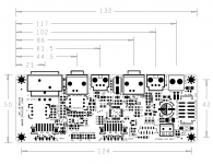
Here is the detail SPDIF board PCB dimensions, just hope it helps.
Regards,
Ian
Attachments
Set up 3.2V LiFePO4 direct battery PSU as a reference for Si570
As I mentioned a couple of weeks ago, the key thing to Si570 is the PSU. But to achieve a better result, what we need to do the first is setting up a reference. Each change will get compare with the reference to decide improved or not.
LiFePO4 battery cell is a good candidate. The 3.2V output can power si570 board directly. Battery comes with very low noise. But it doesn’t mean battery must be the best, because noise comes from three parts: DC power, regulator (include voltage reference) and the load. Battery wires and the high frequency active load can still make noise.
To power si570, higher capacity battery cell would be a better choice. I got a couple of 26650. I wanted to source some A123, but A123 was discontinued for a long time. I don’t think the ones I’m using are as good as A123, for I just use them as reference, so I don’t concerned much about that.
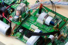
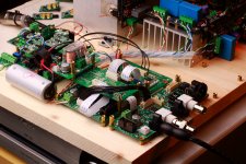
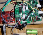
Steps (Please see the pictures for details):
1. Short the input and output of external LDO connector with a jumper (included in the KIT).
2. Must include an isolator board between FIFO and the clock board.
3. Connecting one LiFePO4 battery cell to the DC input connector J2 of the si570 board via a battery management board.
Some comments:
1. Magnet ring is suggested for the battery cable because the load frequency could be very high and wires are too long in this case.
2. If it is possible, try to monitor the battery by a passive voltage meter to avoid any damage caused by over discharge.
As I mentioned a couple of weeks ago, the key thing to Si570 is the PSU. But to achieve a better result, what we need to do the first is setting up a reference. Each change will get compare with the reference to decide improved or not.
LiFePO4 battery cell is a good candidate. The 3.2V output can power si570 board directly. Battery comes with very low noise. But it doesn’t mean battery must be the best, because noise comes from three parts: DC power, regulator (include voltage reference) and the load. Battery wires and the high frequency active load can still make noise.
To power si570, higher capacity battery cell would be a better choice. I got a couple of 26650. I wanted to source some A123, but A123 was discontinued for a long time. I don’t think the ones I’m using are as good as A123, for I just use them as reference, so I don’t concerned much about that.
Steps (Please see the pictures for details):
1. Short the input and output of external LDO connector with a jumper (included in the KIT).
2. Must include an isolator board between FIFO and the clock board.
3. Connecting one LiFePO4 battery cell to the DC input connector J2 of the si570 board via a battery management board.
Some comments:
1. Magnet ring is suggested for the battery cable because the load frequency could be very high and wires are too long in this case.
2. If it is possible, try to monitor the battery by a passive voltage meter to avoid any damage caused by over discharge.
Attachments

Last edited:
I wanted to source some A123, but A123 was discontinued for a long time.
Hi Ian,
i´ve got my A123 ANR26650m1-B yesterday!
Didn´t you have a A123 source in Canada?
Best,
Oliver
Attachments
Last edited:
Hi Ian,
i´ve got my A123 ANR26650m1-B yesterday!
Didn´t you have a A123 source in Canada?
Best,
Oliver
Hi Oliver,
I can not source any A123 26650 in Canada. Where did you get yours?
Is there any possible I buy a couple from your? But the problem is how can you ship batteries to Canada? 🙂
Regards,
Ian
It is possible if you write on the box that they're not restricted, if these actually are not restricted.
Check "provision a67" and "special provision 238 adr" and "un 2800".
I also can't source these batteries. I have sent 2 emails to a123 about resellers but received nothing back.
Check "provision a67" and "special provision 238 adr" and "un 2800".
I also can't source these batteries. I have sent 2 emails to a123 about resellers but received nothing back.
Finding a source of genuine a123s is almost impossible... I had to buy one of those DeWalt 36V batteries to make sure the ones I use for the precious DACs are OK, that is a way for a DIY guy who doesn't need more than a few to get them fast and expensive 🙁
Do you mean the battery pack for drills? Nice! I didn't know those had a123 inside!
Edit: I see some very bad reviews on amazon.com
Edit: I see some very bad reviews on amazon.com
Yes, battery packs for drills, I am not sure if the new ones are the same but mine had 10pcs. of a123 cells inside that were genuine for sure. The packs do fail a lot though but when they work the DeWalts are simply monsters. A123 had some bigger batteries too that held great promise in a lot of areas, it was really sad they went down.
Hi Oliver,
I can not source any A123 26650 in Canada. Where did you get yours?
Is there any possible I buy a couple from your? But the problem is how can you ship batteries to Canada? 🙂
Regards,
Ian
Hi Ian,
i have posted a few informations in my blog about my source 😉
- Home
- Source & Line
- Digital Line Level
- Asynchronous I2S FIFO project, an ultimate weapon to fight the jitter