Rookakoma, that is a superbly thought out amp project. So many creative touches !
Is the modular output stage your design along with those pretty little red boards ?
Is the modular output stage your design along with those pretty little red boards ?
Thank You!
The amplifiers are fully my design with PCB's.
The modular output stage ideas comes from Cortez (an another hungarian DIYAudio member).
Gerber files are available for private request, if you want to use it.
Cheers!
The amplifiers are fully my design with PCB's.
The modular output stage ideas comes from Cortez (an another hungarian DIYAudio member).
Gerber files are available for private request, if you want to use it.
Cheers!
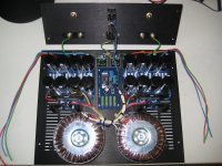
Another F5 with beefier PSU's
Finally finished my F5, it was a lot of work and fun, and it sounds fantastic. Nothing like I have ever earned before...
Lot of thanks to Nelson Pass and all other forum members for all the tips and articles posted.
I've been reading for days, maybe weeks, but it was fun and I learned a lot.
I have a lot of pictures to post 😀
The amp is dead quiet, not the slightest hum, and I can't hear any noise with my ear at the tweeter.
All the boards are from DIYAudio to support the forum 🙂 and they are great nice boards.
Here are some pic's:
Attachments
-
 dual PSU.JPG629.1 KB · Views: 1,816
 -
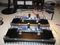 both finished.jpg547.4 KB · Views: 771
 -
 first board finished.jpg530.4 KB · Views: 704
 -
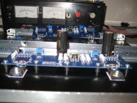
 closeup3.jpg753.7 KB · Views: 680
 -
 first board almost ready.jpg430.7 KB · Views: 724
 -
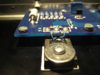
 thermal glue on leg.jpg753.7 KB · Views: 1,458
 -
 special ntc first ampboard.jpg504.6 KB · Views: 1,469
 -
 tapping.jpg414.8 KB · Views: 1,576
 -
 closeup psu.JPG614.1 KB · Views: 1,706
 -
 thermally connected, very nice soldering joints.jpg629.4 KB · Views: 764
And some more pic's of the finished F5......
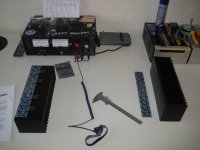
The last foto is my next project: the F5 Turbo v2 with bigger Austerlitz KS300.6 heatsinks, 2sj201 / 2sk1530's and I want to do the EUVL trick with the extra 5 Ohms resistor in the 2SJ74's source. Also truing to build the chassis myself with the heatsinks I have. So again a lot of work to come...😎
Thanks again for all your knowledge 😀
Attachments
-
 front with cover.jpg372.7 KB · Views: 593
 -
 with cover.jpg440.1 KB · Views: 619
 -
 making music.jpg540.7 KB · Views: 585
 -
 backside.jpg424.1 KB · Views: 493
 -
 back2.jpg308.2 KB · Views: 594
 -
 all that gold.jpg525.1 KB · Views: 630
 -
 inside2.jpg540 KB · Views: 571
 -
 inside.jpg694 KB · Views: 733
 -
 overview.jpg752.8 KB · Views: 832
 -
 next project.jpg424 KB · Views: 731
Your solder joints look perfect. Great Job on the entire build. I'm always interested in what speakers are being driven. Got any info?
Hi Bob,
Thanks!
I have very old B&W DM600i's and the bigger ones DM610i's.
But I'm planning on building new speakers myself, they are a kit from a dutch store and are called 'Scanspeak mini monitor' Or the reference monitor, or the Vifa Column MK2, but i have to do more listening over there, to decide.
Cheers, Walter
Hi Marra,
I don't know the make and type of these sinks but i got them from www.dickbest.nl in Amsterdam.
I went to their nice, little store and selected them.
The sinks are not on their website. Cost Euro 1,20 a piece.
Walter
I don't know the make and type of these sinks but i got them from www.dickbest.nl in Amsterdam.
I went to their nice, little store and selected them.
The sinks are not on their website. Cost Euro 1,20 a piece.
Walter
WALTERW
congratulations for your work, where you buy the amp chassis
greetings from chile all
congratulations for your work, where you buy the amp chassis
greetings from chile all
Thanks Walter unfortunately neither RS or Farnell have anything like those on there sites.
Really nice build by the way.
Really nice build by the way.
And some more pic's of the finished F5......
The last foto is my next project: the F5 Turbo v2 with bigger Austerlitz KS300.6 heatsinks, 2sj201 / 2sk1530's and I want to do the EUVL trick with the extra 5 Ohms resistor in the 2SJ74's source. Also truing to build the chassis myself with the heatsinks I have. So again a lot of work to come...😎
Thanks again for all your knowledge 😀
Wow, that is a great build! Congrats
🙂
dickbest
Dick is a fun guy.
In the early days of his shop, he told me I offered way too much for his parts, so he charged me half.

(excellent looking project, nice to see the babies nested, and so quick)
Hi Bob,
...........
But I'm planning on building new speakers myself, .............
Cheers, Walter
Since you are going to build, let me suggest you take a look at the "Sunflowers". They are premium output devices at a very reasonable cost. I've built around fifteen different designs over thirty years and I most likely will stop with these.
You're correct AudioSan! 3U300 with alu backplate and 10mm frontplate... Just enough cooling for a F5.
Heatsinks get around 48 degrees Celsius at 1.3 Ampere bias.
I tried to bias them at 1.75 Ampere each, but that was too much for the heatsinks...
Heatsinks get around 48 degrees Celsius at 1.3 Ampere bias.
I tried to bias them at 1.75 Ampere each, but that was too much for the heatsinks...
Thanks Bob, done some reading, I like the Sunflowers... but they are way to big for my livingroom, the WAF is too low 😀
I need some small high quality speakers...
I need some small high quality speakers...
I had the same problem several years ago, so I traded my WAF in for a pair of Kliscphorns. Seems to have worked out just fine. 😀
Wont go off topic any more after this, but the Overnight Sensation have a great reputation. Same designer.
Wont go off topic any more after this, but the Overnight Sensation have a great reputation. Same designer.
Last edited:
Pass F5 turbo build
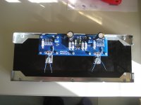
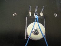
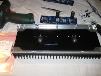
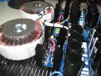
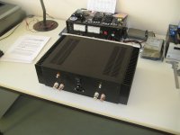
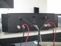
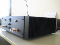
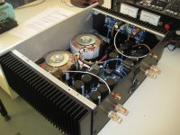
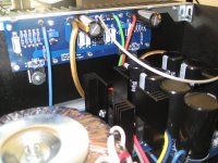
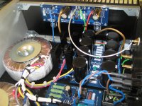
I built this Pass F5 turbo V2 for a friend, biased 0.55A/device on 33V rail. Caps are 4 X 15000µF /rail making total 120,000µF/channel . Toroidal trafo 4 X 24-0 secondaries for transformer making total 1KVA and PCB designed by me for 15 people in Indian forum GB.
Aluminum box is handmade using hacksaw, power drill and set of files; except anodizing.


More coming in F5 Turbo builder's thread.
I built this Pass F5 turbo V2 for a friend, biased 0.55A/device on 33V rail. Caps are 4 X 15000µF /rail making total 120,000µF/channel . Toroidal trafo 4 X 24-0 secondaries for transformer making total 1KVA and PCB designed by me for 15 people in Indian forum GB.
Aluminum box is handmade using hacksaw, power drill and set of files; except anodizing.
View attachment 330517 View attachment 330518 View attachment 330519
More coming in F5 Turbo builder's thread.
Is the mains transformer located underneath the large capacitors' PCB?
Is the mains transformer located underneath the large capacitors' PCB?
Yes, those power filter PCBs are elevated above transformer. There is 3/4" gap between transformer and PCBs.
- Home
- Amplifiers
- Pass Labs
- Pictures of your diy Pass amplifier