A75?
Norb
Sounds like a possibility. Can you please point me to the A75 thread? Also, is this avaliable in kit form?
I have also been reading up on passive pre's. Any thoughts on how these would perform?
TC
Best wishes
TC
Norb
Sounds like a possibility. Can you please point me to the A75 thread? Also, is this avaliable in kit form?
I have also been reading up on passive pre's. Any thoughts on how these would perform?
TC
Best wishes
TC
Dear TC,
maybe the A75 would be an option for you, as you can alter the sonic characteristic of this amp in a large range.
I tried different values for some components as suggested in the A75 article (feed-back amount and folded cascode operation) and the amp could be made very mellow and softly sounding (Speakers are Isophon Europa).
Since i´m more the rocking kind, i set up the amp in the opposite soundwise, but the difference in sound characteristic was amazing, espacially voices and classical music could be made like honey: sweet, soft and golden.
Norb
Pass A40 Monoblocks
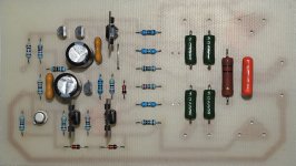
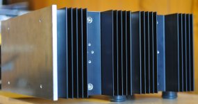
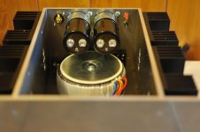
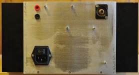
Hello to all, this is my first post on this great audio forum. Thought I would share a few photos of my Pass A40 project. First of all I would like to say thanks very much for the many hints and tips I've picked up from all who have built this amplifier. I have spent many hours reading loads of posts and have finally registered as a member of the forum.
My amps are still "work in progress" but are getting ever closer to completion after a busy two week christmas break spent mostly in my dads workshop. PCBs are built and metal work 99% finished; just cosmetics and case top and bottom to sort out before internal wiring up can commence.
Heatsinks are 0.5 deg c / watt per output transistor; mains transformer is 500va; smoothing caps are both 22000uF.
Hoping to build a B1 buffer next but I was wondering if anyone knows,
A) What is the input sensitivity of the A40 for full output,
B) Can the amps run with approx +/- 40V rails (my transformer secondaries are 25V and I have replaced the JFET with 2N4392,
C) Could the output stage bias be increased to 2 amps. My speakers are 4 ohms and the A40 will move into class AB at 20 watts into this load.
Maybe these are really questions for Nelson Pass.
Many thanks to everyone. I will post again when the project is complete and include a gerber file for my PCB which I layed out using the excellent "Free PCB" program .
Attachments
Hi,
a little bit teasing!
Test building!
And, we will see if it fit ...
a little bit teasing!
Test building!
An externally hosted image should be here but it was not working when we last tested it.
And, we will see if it fit ...
An externally hosted image should be here but it was not working when we last tested it.
An externally hosted image should be here but it was not working when we last tested it.
An externally hosted image should be here but it was not working when we last tested it.
Sorry,
but i see the pics (here as a screenshot9.
Any problems, please report. I will search another provider.
but i see the pics (here as a screenshot9.
An externally hosted image should be here but it was not working when we last tested it.
Any problems, please report. I will search another provider.
Last edited:
Carsten - The photos are still not viewing, but your sample screenshot did have the photos...
?
Please try again, your project looks wonderful from the little I can see of it. 😀 😀 😀
?
Please try again, your project looks wonderful from the little I can see of it. 😀 😀 😀
Hi,
ok, i think, i now where is the problem. I show these pictures in another forum and link it to here. Next try.
- Test building
-That is what i want ......
Hope now it is better. 😱 And more pictures i will show you when i am finished ....
How it sounds? ............😀
ok, i think, i now where is the problem. I show these pictures in another forum and link it to here. Next try.
- Test building
An externally hosted image should be here but it was not working when we last tested it.
An externally hosted image should be here but it was not working when we last tested it.
-That is what i want ......
An externally hosted image should be here but it was not working when we last tested it.
An externally hosted image should be here but it was not working when we last tested it.
An externally hosted image should be here but it was not working when we last tested it.
Hope now it is better. 😱 And more pictures i will show you when i am finished ....
How it sounds? ............😀
Hoping to build a B1 buffer next but I was wondering if anyone knows,
A) What is the input sensitivity of the A40 for full output,
B) Can the amps run with approx +/- 40V rails (my transformer secondaries are 25V and I have replaced the JFET with 2N4392,
C) Could the output stage bias be increased to 2 amps. My speakers are 4 ohms and the A40 will move into class AB at 20 watts into this load.
Maybe these are really questions for Nelson Pass.
Earthloop: Nice work so far! I suggest asking your questions in a separate A40 thread (new or existing), as I get the feeling we're trying to keep this thread as a pics-only thread....
Ugly Duckling in the Water
Here is a proof of concept project to incorporate water cooling for computers into a discrete power amp build. There was a successful build with a LM3886 project, but that is a big overshoot.
This type of amp might benefit more with this technique. To stay in the spirit of this thread I'll post subsequent developments and photos on that other thread.
The basic block is built from generic locally and widely available stock. The major element is 1/4" x 3" x 17" aluminum. Mine was cut from a piece of 3x3 angle but a company like Metals Depot has about all one would need. The 1/2" x 1/2 " channel was selected because it provided more "fins" per unit/mounting screw.
 [/IMG]
 [/IMG]
The box is from a sheet of 3/8" Plexiglas cut on a table saw with connecting edges polished to 1600 grit wet sandpaper - then glued together with Plastruct Liquid Cement. Metal to Plexiglas meet with a thin automotive paper gasket with Goop on both sides. Blind threaded holes with 6-32 screws were used along with 1/16" x 1/2" angle for reinforcement. For safety reasons the cooling system must be self-contained and completely separate from the amp.
 [/IMG]
The power transistor mounting plate is attached with 8-32 screws into more blind tapped holes in the waterblock.
 [/IMG]
 [/IMG]
The stilts were installed as I thought I would place the cooling system under the amp, but decided I needed to make sure it would work before going to all that trouble.
 [/IMG]
Success - Amp - cooler combination in full operation in a complete system.
 [/IMG]
These readings were done with simple IR gun (I bought a new meter with a thermocouple but I put that part somewhere I wouldn't loose it, and....🙄) so they aren't exact or scientific. There is enough information though to warrant proceeding to the next phase as well as learning where the heat transfer can be improved. I suspect I'll be able to use a smaller pump and radiator/fan and still get the efficiency needed.
 [/IMG]
Readings
The air cooling readings are on the partially "de-feathered" ugly duckling with a few new parts and shorter wires.
 [/url][/IMG]
 [/IMG]
Sound wise - the new Audyn Plus input caps have produced a huge improvement in the brightness and stage of the amps. Several other parts upgrades will follow shortly.
 [/url][/IMG]
BTW - the next phase will be cutting/folding the water block in half to avoid the 17" dimension for better placement (hidden) inside a chassis. Something like this:
 [/url][/IMG]
 [/url][/IMG]
Here is a proof of concept project to incorporate water cooling for computers into a discrete power amp build. There was a successful build with a LM3886 project, but that is a big overshoot.
This type of amp might benefit more with this technique. To stay in the spirit of this thread I'll post subsequent developments and photos on that other thread.
The basic block is built from generic locally and widely available stock. The major element is 1/4" x 3" x 17" aluminum. Mine was cut from a piece of 3x3 angle but a company like Metals Depot has about all one would need. The 1/2" x 1/2 " channel was selected because it provided more "fins" per unit/mounting screw.
The box is from a sheet of 3/8" Plexiglas cut on a table saw with connecting edges polished to 1600 grit wet sandpaper - then glued together with Plastruct Liquid Cement. Metal to Plexiglas meet with a thin automotive paper gasket with Goop on both sides. Blind threaded holes with 6-32 screws were used along with 1/16" x 1/2" angle for reinforcement. For safety reasons the cooling system must be self-contained and completely separate from the amp.
The power transistor mounting plate is attached with 8-32 screws into more blind tapped holes in the waterblock.
The stilts were installed as I thought I would place the cooling system under the amp, but decided I needed to make sure it would work before going to all that trouble.
Success - Amp - cooler combination in full operation in a complete system.
These readings were done with simple IR gun (I bought a new meter with a thermocouple but I put that part somewhere I wouldn't loose it, and....🙄) so they aren't exact or scientific. There is enough information though to warrant proceeding to the next phase as well as learning where the heat transfer can be improved. I suspect I'll be able to use a smaller pump and radiator/fan and still get the efficiency needed.
Readings
The air cooling readings are on the partially "de-feathered" ugly duckling with a few new parts and shorter wires.
Sound wise - the new Audyn Plus input caps have produced a huge improvement in the brightness and stage of the amps. Several other parts upgrades will follow shortly.
BTW - the next phase will be cutting/folding the water block in half to avoid the 17" dimension for better placement (hidden) inside a chassis. Something like this:
Last edited:

Nice well thought out.
Not looking for a spoon feed on this question. Ill do a search if its a yes.
Has anyone done cooling using transformer oil?
I've got a ton of the light super nonconductive/high temp oil for cooling big transformers.
Not looking for a spoon feed on this question. Ill do a search if its a yes.
Has anyone done cooling using transformer oil?
I've got a ton of the light super nonconductive/high temp oil for cooling big transformers.
concept project
Why go to all that trouble when a professional fluid heat exchanger plate can be had for little dollars, and superior in every way to your contraption.
Size and construction of your aquarium suggest little knowledge of fluids and thermodynamics.
Why go to all that trouble when a professional fluid heat exchanger plate can be had for little dollars, and superior in every way to your contraption.
Size and construction of your aquarium suggest little knowledge of fluids and thermodynamics.
He might like the building and learning process! 🙂
That said, what's sort of Comercial available unit would you propose for such a build?
Think I posted the following picture half a dozen times already.(up to 3-4ft length if so desired)
In Europe, at vendors as Burklin in germany.
In the US, think McMaster&Carr.
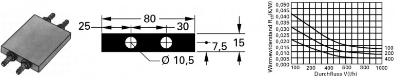
See If you can spot the significant differences between that one and bcmbob's cooler.
In Europe, at vendors as Burklin in germany.
In the US, think McMaster&Carr.
See If you can spot the significant differences between that one and bcmbob's cooler.
Attachments
Thanks sakellogg.
MASantos is right on point. It's all part of the DIY challenge. After about ten years of liquid cooling CPU projects, with a lot of Plexiglas and metal in the stash, I wanted to use what was on hand. Thinking it through is half the fun
jacco, if you look at the "LM3886 Project" link at the top of the first post you will see I did use something quite similar to what you are suggesting. I also considered pizio blocks but you still have to deal with removing the residual from the hot side. The 1/4" aluminum is an intentional overbuild as I had no prior experience with the reported high heat of a discrete amp. You know - "No matter how many times I cut it, it's still too short" 😀 The biggest problem was the thin walls on that cooler. One would still have to use a plate of at least 3/8", or a sophisticated clamping system for mounting the power transistors.
6L6 suggested if I had four power transistors I would be in the area of four 100W light bulbs. I did an initial test with a 500W halogen bulb to see if I was in the ballpark.
No doubt there are thousands of successful air cooled discrete builds, and some of the giant heat sink amps have a big aesthetic appeal on their own - just plain impressive in mass alone. This is just a trial of a different approach.
Here is a fun little video of the flow pattern:
Water Spread
Flows from canter, then side to side and back out the center. Not a perfect isolation but enough to hold uniformity across the plate.
Last edited:
- Home
- Amplifiers
- Pass Labs
- Pictures of your diy Pass amplifier