I have yet to try the version with no degeneration, but i liked minimal degeration. When i rebuild mine, i will use the version woth no Rs on FE or output, possibly doubling up on onput jfets and adding cascoded bjt to FE, like ZM posted early.
Have you compared Onetics with Jensen?
Have you compared Onetics with Jensen?
I need to go back to the no degeneration version so as to maintain a baseline.
Relatively easy to switch.
Also might try what Nelson suggested in his article ( 0 and .05 ohms )
Multiple pairs sound interesting
Waiting for a board to do comparison between Jensen and Onetics - my hand wiring just isn't that good - I'm very slow
Separate note - FETs arrived thanks !!!!
Relatively easy to switch.
Also might try what Nelson suggested in his article ( 0 and .05 ohms )
Multiple pairs sound interesting
Waiting for a board to do comparison between Jensen and Onetics - my hand wiring just isn't that good - I'm very slow
Separate note - FETs arrived thanks !!!!
Another factor to consider beyond source degeneration is the effect due to unmatched R100 JFETs. My left channel appears to have very well matched JFETs and behaves much like LTSPICE simulations predict. In the right channel I have swapped around between 4 other R100s and cannot get simlar performance. The major difference is that the 3rd harmonic is much higher than with the left channel. The measured transconductances my R100s at 1.4A bias current do not appear to explain the behaviour that I am seeing. I am at a loss to explain why the 3rd harmonic differs so much.
Another factor to consider beyond source degeneration is the effect due to unmatched R100 JFETs. My left channel appears to have very well matched JFETs and behaves much like LTSPICE simulations predict. In the right channel I have swapped around between 4 other R100s and cannot get simlar performance. The major difference is that the 3rd harmonic is much higher than with the left channel. The measured transconductances my R100s at 1.4A bias current do not appear to explain the behaviour that I am seeing. I am at a loss to explain why the 3rd harmonic differs so much.
My friend dsdjoy combined his 8 SS in all combinations in a MU follower arrangement. Out of 30 measured combinations only four delivered the wanted distortion spektra without change of the circuit design or Zen Pot.
So there seems to be much unsecurity in the results using these parts....May be you PM him.
Last edited:
generg: A close look at the F6 finished product by Mr. Pass, shows the absence of user-adjustable Zen Pots on the front panel. The last picture of his article clearly shows the inside of F6. No Zen Pots therein either. The blue-turquoise parts are most probably the 5K pots to tweak bias and zero the output offset. It appears that Mr. Pass did not use Zen Pots.My friend dsdjoy combined his 8 SS in all combinations in a MU follower arrangement. Out of 30 measured combinations only four delivered the wanted distortion spektra without change of the circuit design or Zen Pot.
So there seems to be much unsecurity in the results using these parts....May be you PM him.
Missing from the preceeding posts is via this question: What is the objective and subjective performance of one's diyF6 without Zen Pots? This is the baseline to introduce changes and determine their value on performance. I believe lhquam did some baseline characterization early on in his development; but quickly embraced using Zen Pots, and did not return to his baseline since.
N.B. Could the PCB be double-sided with 2 additional pots on the underside?
Last edited:
I think that differences between the internal source resistance of the FETs might explain the differences in H3.
Lhquam, don't mismatched fets result in H2 and not H3 ?
Would this affect drain impedance, and along with it, the ability to use loadline cancellation as Nelson talks about.
According to Mr. Pass, distortion in the dynamic sense emanates from a bjt, a FET etc. due to variation in its gain as it delivers power to the load. Variable gain is due to the changing current passing through the device and the changing voltage across its terminals as it does its job.I think that differences between the internal source resistance of the FETs might explain the differences in H3.
There is a high probability that Mr. Pass also characterizes the distortion characteristics of each power JFET, ans selects those which fit.
You have the skills and the tools to characterize the distortion of each power JFETin Teaser-6. For example:
- Disable loop feedback
- No load
- Disconnect the secondary winding of the transformer's input to the bottom JFET
- Connect its bias drive. The bottom JFET is now a constant current source to the upper JFET. The variable due to the current passing through the upper JFET [affecting its gain] is nulled.
- Input signal [1KHz] at many output amplitudes to a peak value at +-20 V
- Measure the distortion of the upper JFET due to variation of Vds.
- Enable loop feedback and measure distortion at the same output levels used earlier.
- Repeat all of the above using the lower JFET as the gain device and the upper JFET as its constant current load.
- The constant current of 1.4 A at idle can be changed in the range of 0.4 A minimum to 2.4 A maximum to simulate 2 Ap-p delivered to the load . The linearity of the output signal is the outcome
The 1978 article by Mr. Pass which is entitled "Cascode Amp design" is a must read to understand and characterize the distortion of then a power NPN bjt. In our case, cascoding locks Vds to a constant value during operation but allows for current variations.
A possible idealized output amplifying device in a theoretical diyF6 maybe an NPN-STASIS (TM). It is made up of a power NPN transistor operating in Class A driving 4 or more PNPs. One set is needed for the upper and another identical set for the lower power output positions. However, the input impedance of each NPN is low compared to that of JFET. Nonetheless, this arrangement locks the variation of the current flowing through the input NPN in charge of defining net distortion to a constant.
I can envision replacing each on the NPNs operating in constant current mode with IRFP240s doing the same in a "clone STASIS (TM)"; clearly bending backwards to accomodate the diyF6 JENSEN.
Update 2
First of all resistance measurements I gave in previous post were high - forgot to subtract lead resistance.
Took out the pots and R13, R14 to calibrate my ears with zero resistance on SSs
Listened for a couple hours and then did R13 =0 and R14 = .05 ohms. After that I reversed R13 and R14. To my ears with R13 =0 and R14 = .05 soundstage was forward. Reversing the resistors moved it back. When Nelson said a small amount of resistance added to SSs I think he meant it. It doesn't take much to change things.
I'm back to no degeneration - it sounds best to my ears and with the other amps in my tri-amp.The voices sound really natural - there is good slam and detail. I would love to hear F6 with a 100dB system like LaScala
Again thanks to all that have helped - may learn how to take some measurements with the Mac.
buzzforb - If no boards become available I will hand wire the Jensens.
Best
Happy you had succes...! 🙂🙂
Yes measuring the channels to see if they have a very different distortion spectra is a good idea.
I repeat, my left channel had k3 and k2 on the same level, right channel had k2 clearly higher. Seems to depend on on the SS pairs...
Yes measuring the channels to see if they have a very different distortion spectra is a good idea.
I repeat, my left channel had k3 and k2 on the same level, right channel had k2 clearly higher. Seems to depend on on the SS pairs...
Thank you for everything - measurements are up next - resurrected my Waveterminal U24 and I will go from there.
Update 2
First of all resistance measurements I gave in previous post were high - forgot to subtract lead resistance.
Took out the pots and R13, R14 to calibrate my ears with zero resistance on SSs
Listened for a couple hours and then did R13 =0 and R14 = .05 ohms. After that I reversed R13 and R14. To my ears with R13 =0 and R14 = .05 soundstage was forward. Reversing the resistors moved it back. When Nelson said a small amount of resistance added to SSs I think he meant it. It doesn't take much to change things.
I'm back to no degeneration - it sounds best to my ears and with the other amps in my tri-amp.The voices sound really natural - there is good slam and detail. I would love to hear F6 with a 100dB system like LaScala
Again thanks to all that have helped - may learn how to take some measurements with the Mac.
buzzforb - If no boards become available I will hand wire the Jensens.
Best
Mine will be played on my ALtec system which should come in at about 98dB@1W😀
AS for degerneration. It is interesting to me that such a small amout of degernation could have so much affect, but I agree with you. THere is something that is truly freed in the music wthout it, but youe must really work to find the balance considering overall distortion as well. I wonder if this is a situation where reall y high quality source resistors would be in order. My question is the difference in sound a result of performance parameters chaging, ie more global feedback or does this circuit really reveal parts? Did you go without degeneration on the FE?
I think you are missing the point. The primary source of distortion in any FET amplifier is due to the square law nonlinearity of the devices. Any feedback, whether a global loop or local source degeneration introduces higher order distortion components.
The figure below shows a mathematical derivation of the harmonic components of a single ended FET common source amplifier with degeneration. The coefficients a powers of v, v^i correspond to the magnitudes of the corresponding harmonics. In a push-pull amplifier, the even harmonics tend to cancel if the device parameters and Rs are properly matches and/or adjusted. The important point of this derivation is that the odd harmonics can be reduced by minimizing Rs.
The figure below shows a mathematical derivation of the harmonic components of a single ended FET common source amplifier with degeneration. The coefficients a powers of v, v^i correspond to the magnitudes of the corresponding harmonics. In a push-pull amplifier, the even harmonics tend to cancel if the device parameters and Rs are properly matches and/or adjusted. The important point of this derivation is that the odd harmonics can be reduced by minimizing Rs.
The 1978 article by Mr. Pass which is entitled "Cascode Amp design" is a must read to understand and characterize the distortion of then a power NPN bjt. In our case, cascoding locks Vds to a constant value during operation but allows for current variations.
A possible idealized output amplifying device in a theoretical diyF6 maybe an NPN-STASIS (TM). It is made up of a power NPN transistor operating in Class A driving 4 or more PNPs. One set is needed for the upper and another identical set for the lower power output positions. However, the input impedance of each NPN is low compared to that of JFET. Nonetheless, this arrangement locks the variation of the current flowing through the input NPN in charge of defining net distortion to a constant.
I can envision replacing each on the NPNs operating in constant current mode with IRFP240s doing the same in a "clone STASIS (TM)"; clearly bending backwards to accomodate the diyF6 JENSEN.
Attachments
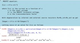
The important point of this derivation is that the odd harmonics can be reduced by minimizing Rs.
😀
Mine will be played on my ALtec system which should come in at about 98dB@1W😀
AS for degerneration. It is interesting to me that such a small amout of degernation could have so much affect, but I agree with you. THere is something that is truly freed in the music wthout it, but youe must really work to find the balance considering overall distortion as well. I wonder if this is a situation where reall y high quality source resistors would be in order. My question is the difference in sound a result of performance parameters chaging, ie more global feedback or does this circuit really reveal parts? Did you go without degeneration on the FE?
No degeneration on the front end - the Idss is 8.5
I just used the 5% Stacpole Metal oxides I had here - paralleled .1 ohm resistors
jameshillj has commented on resistors in the F3 thread I believe - He used Isabellenhuette as I remember.
I think you are missing the point. The primary source of distortion in any FET amplifier is due to the square law nonlinearity of the devices. Any feedback, whether a global loop or local source degeneration introduces higher order distortion components.
The figure below shows a mathematical derivation of the harmonic components of a single ended FET common source amplifier with degeneration. The coefficients a powers of v, v^i correspond to the magnitudes of the corresponding harmonics. In a push-pull amplifier, the even harmonics tend to cancel if the device parameters and Rs are properly matches and/or adjusted. The important point of this derivation is that the odd harmonics can be reduced by minimizing Rs.
Thanks lhquam, you have the gift of such skills I can only wish and imagine to have. Please strike off the above clone STASIS (TM) idea with MOSFETs.
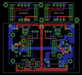
So, with Nelson's approval, I will try to post something close to the following for sale after a prototype is made and built.
It will use a daughter card concept to add in a Onetics or Jensen transformer, or allow a Perfboard to be mounted on the 2x10 2.54 Male pins to roll your own transformer onto it.
It will have all four pots and will be based on the F6 Second Harmonic. If one wants a simpler versions than jumpers need to be put in place for it. It may not be for everyone, but it will reach market, pending approval and I don't get hit with a snowplow or something.
Attachments
- Home
- Amplifiers
- Pass Labs
- F6 Amplifier