This style of voltage drop results in a very variable relay coil voltage.
Low mains voltage may not trigger the relay. High mains voltage may overheat the relay.
Low mains voltage may not trigger the relay. High mains voltage may overheat the relay.
What's wrong with 470uF.
There are millions, if not billions, manufactured and sold around the world and they can't all be bad.
There are millions, if not billions, manufactured and sold around the world and they can't all be bad.
I think he mean
is it better to put big 10.000uF than just a tiny 470uF 😀 ???
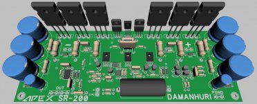
Anyway nice 3D @DAMANHURI
I hope you can realize it soon.
I just finished etching one PCB, manual draw as usual 🙂
I really want to finnish it as soon as posible.
Regards
is it better to put big 10.000uF than just a tiny 470uF 😀 ???
Anyway nice 3D @DAMANHURI
I hope you can realize it soon.
I just finished etching one PCB, manual draw as usual 🙂
I really want to finnish it as soon as posible.
Regards
I'm waiting for your SR200 John, I now again a lot of work in my office and make it happen soon, I have not check the PCB track I doubt there is something wrong.I think he mean
is it better to put big 10.000uF than just a tiny 470uF 😀 ???
Anyway nice 3D @DAMANHURI
I hope you can realize it soon.
I just finished etching one PCB, manual draw as usual 🙂
I really want to finnish it as soon as posible.
Regards
Standars value SR200
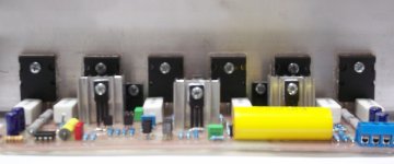
Hi all, thanks to apexaudio for great schematic...
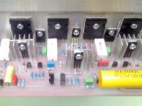
Finally I made SR200 with same value with schematic, here some pictures
(but sorry picture is not good quality)
I use 220nF/63V on VBE & 100pF/100V on colector of the driver transistor
because that what I get here, so what is the maximum voltage that I can use?
Regards
Hi all, thanks to apexaudio for great schematic...
Finally I made SR200 with same value with schematic, here some pictures
(but sorry picture is not good quality)
I use 220nF/63V on VBE & 100pF/100V on colector of the driver transistor
because that what I get here, so what is the maximum voltage that I can use?
Regards
Attachments
..... size of PCB it's 162 mm x 65 mm . 🙂
Regards Alex.
How about the sound 😀
you got to build it

Hi Mile ,
Yes it's my mistake, it was late and sleepy, but I corrected the error, now I think it's good.
Regards Alex.🙂
Such that other power as given in: 😕
4 ohm
8ohm
Hi Mile ,
Yes it's my mistake, it was late and sleepy, but I corrected the error, now I think it's good.
Regards Alex.🙂
My old amp have 'normal' and 'direct' inputs
super nice, which part is the pcb.😀
wonderful project. 😱😱
PCB in progres...
please upload:😉
the schematic diagram
the pcb
the pcb, to do with the method of the plate.😀
that part is the design of alex 😕Hello,
OK, I have not paralleled the resistor to inductor, Will do it.
Alex I mounted the transistors, and connected to psu.
Fired up and connected to mobile phone---- No sound.
Mobile disconnected Touch input pin with hand it make lots of noise and 22e resistor on psu gets extremely hot.
Checked all the connections.
Checked for shorts- No shorts.
Checked transistors for short to heat Sink- No short.
Disconnected speaker gnd from psu gnd- Psu resistor does not get hot, Connect again gets hot.
what Could be the problem.
And how do I Measure and adjust the Bias, Please Show exact procedure, I have never done it before.
to download 😀
Hi all, thanks to apexaudio for great schematic...
Finally I made SR200 with same value with schematic, here some pictures
(but sorry picture is not good quality)
I use 220nF/63V on VBE & 100pF/100V on colector of the driver transistor
because that what I get here, so what is the maximum voltage that I can use?
Regards
Jhon, I Like Your Drawing.
Nice design
Hi Mas John bali... your pcb design is very nice... I like every your design... there's alot of space to put the componen and the heatsink .. I plan to build the stereo SR 200 using your pcb layout... can you send me the pdf file sir.. couse I make the pcb using the iron .. sorry for my english..🙂🙂Hi all, thanks to apexaudio for great schematic...
Finally I made SR200 with same value with schematic, here some pictures
(but sorry picture is not good quality)
I use 220nF/63V on VBE & 100pF/100V on colector of the driver transistor
because that what I get here, so what is the maximum voltage that I can use?
Regards
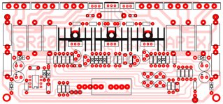
Here pdf & .pcb
Ok, mas Jofual.
this is the pdf for toner transfer.
PCB size is 68mm x 200mm (saya kecilkan sedikit)
& you must set "mirror" setting on the printer.
Do have a laser jet printer?
I don't have & tried photocopier but not good, I end up with "spidol" permanent again 😀 . I will try another way to make PCB.
No component value!
You must find by your shelf where is component value,
because I usually not make it.
I like PCB without silkscreen 🙂
There also .pcb file, but I rename it to .txt
you can try open it with ExpressPCB after rename it again
Enjoy ...
Attachments
Ok, mas Jofual.
this is the pdf for toner transfer.
PCB size is 68mm x 200mm (saya kecilkan sedikit)
& you must set "mirror" setting on the printer.
Do have a laser jet printer?
I don't have & tried photocopier but not good, I end up with "spidol" permanent again 😀 . I will try another way to make PCB.
No component value!
You must find by your shelf where is component value,
because I usually not make it.
I like PCB without silkscreen 🙂
There also .pcb file, but I rename it to .txt
you can try open it with ExpressPCB after rename it again
Enjoy ...
Jhon excellent contribution 🙂
thanks for uploading your work

Greetings from, PERU

Thank mas John ... your pcb design already received.... I like this..thanks a lot bli John....
good space between final transistor and also space for driver transistor so easy to put heatsink...
now ready to make project using photocopy transfaran plastic paper and iron system...and will review the result later..🙂🙂
- Home
- Amplifiers
- Solid State
- Studio Reference Amplifier