I would use voltage rating for C10, C11 > full Vp-p swing of output, about 2x single rail supply voltage.
Voltage of C8 shouldnt be great as it is at Q11 Vce, well under normal conditions i think.
C1 10uf might be difficult to get in small poly package but if you want unpolarised electrolytic they should be easy and small to find.
C4 1uf should be easy to get in unpolarised poly and unpolarised electrolytic.
Thats to comply with schematic showing unpolarised, so I guess that is what is advised.
Last edited:
But does the answer matter to you.
If he comes back and tells us it is 0.1% at -1dB ref clipping, then will that influence you in choosing to build or not.
If it is 0.001% @ -20dB ref clipping, will that help you decide?
I suspect not.
If he comes back and tells us it is 0.1% at -1dB ref clipping, then will that influence you in choosing to build or not.
If it is 0.001% @ -20dB ref clipping, will that help you decide?
I suspect not.
Hi! Mile
You told that alex used two 470k in series instead of 1M C19
Does it make any problem? what changes may occur by decreasing resistance value of c19?
You told that alex used two 470k in series instead of 1M C19
Does it make any problem? what changes may occur by decreasing resistance value of c19?
Last edited:
Hi! Mile
You told that alex used two 470k in series instead of 1M C19
Does it make any problem? what changes may occur by decreasing resistance value of c19?
Two 470k in series is same as 1M.
Alex use two 470k resistor in series insted 1M in DC servo circuit, both is OK.
dear apex,
can you share this sr2oo pcb(bottom).thanks
Two 470k in series is same as 1M.
Hi! Mile
Alex used 4 bc560c where as in sr200 schematic only 3 bc560c are present
why an additional transistor was used ??
Hi! Mile
Alex used 4 bc560c where as in sr200 schematic only 3 bc560c are present
why an additional transistor was used ??
Go to post #32.
Hi Sir APEX can you share SR400 schematic please?
Regards.
SR400 is SR200TEF
Mile
Can I connect input ground to power supply ground directly or I must use 10ohms resistor?
You can connect directly, 10ohms resistor you can add anytime if there is hum or noise.
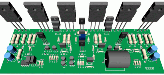
3D preview
Hi all,
I create new layout again, because I can't start make any PCB etched yet.
I hope this is the best I can do, new size is 205 mm x 68 mm
I make it wider so there is enough space between output transistor so the heat can be spread quickly
One more thing is there really good deal if I change the all 2.2uF/100V to the higher value,
I only have 10uF/100V, if bigger is good deal I will change it again 😀
Regards
Attachments
Last edited:
Hi all,
I create new layout again, because I can't start make any PCB etched yet.
I hope this is the best I can do, new size is 205 mm x 68 mm
I make it wider so there is enough space between output transistor so the heat can be spread quickly
One more thing is there really good deal if I change the all 2.2uF/100V to the higher value,
I only have 10uF/100V, if bigger is good deal I will change it again 😀
Regards
Good Job Mr. Jhon.

Nice layout.
But, is it worth squeezing the PCB down to 205 by 45?
That would allow 2 PCBs on a single 205 by 90 board to save costs.
But, is it worth squeezing the PCB down to 205 by 45?
That would allow 2 PCBs on a single 205 by 90 board to save costs.
That can be done, but I like this board
There are space on three TO-126 for the heatsink of course.
I can't find 3D model for heatsink 🙁
For the input caps also enough space for playing with caps 🙂
205 because I bought 205 x 205 board size
divide by 3 = 205 x 68 mm.
I will try it but only one thing...
Do you think larger caps on boards says 470uF will bring much improvement?
If we have enough caps on the main PSU
worth?
Regards
- Home
- Amplifiers
- Solid State
- Studio Reference Amplifier
