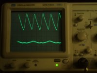
Attached is the ripple traces of the TomChr Regulator. Top trace is Vin ripple of approx 7V p-p and bottom trace is Vout ripple of approx 5mV p-p. The Time is set at 5mS/Div. The rectifier is a 5U4 with a 40uF capacitor. Vin into regulator is 489Vdc and Vout of regulator is set at 394Vdc. The hash on the Vout is approximately at 60kHz and that is why the trace looks fuzzy.
Do you have any idea why the V out ripple has this weird pattern to it repeating every 16 mSec? Any idea why there is a 60kHz oscillation on the output?
Have energized the regulator several times and it starts up smoothly and the measurements are repeatable. Have loaded it to 160 mA with no issue. All I need for the design I am presently doing is 120mA. Temperature of the mosfet case has stayed below 30 deg C on the fan cooled heat sink.
The next plan is to test the regulator with silicon rectifiers as I would prefer to build this power supply without the 5U4.
After this, i will see how it works with the amplifier, not just the dummy resistor load bank.
Attachments
Do you have any idea why the V out ripple has this weird pattern to it repeating every 16 mSec?
1/60 = 16 ms. So what you're seeing is likely the ripple from the op-amp supply feeding through.
Any idea why there is a 60kHz oscillation on the output?
On this schematic: Neurochrome.com : : Audio – High-Voltage Regulator
what are your values for Q1, R4, R10, and C3?
With the values on the schematic (R4 = 2.7 ohm), the regulator will current limit at around 100 mA (or maybe 120 mA). You need to decrease R4 to something like 1.8 ohm if you intend to draw 120 mA continuously. That could be the source of the 60 kHz and weird ripple pattern.
Another potential source of HF oscillations is the gate-source cap of Q1. That's why I added R10 and C3. If decreasing R4 doesn't take care of the 60 kHz, I suggest increasing R10. There should be no HF buzz on the output of the regulator.
But my guess is that the current limiter is playing games with you. That current limiter doesn't play nice. It does the job, but it has fairly high gain, hence, you need to ensure that it never turns on during normal operation.
The next plan is to test the regulator with silicon rectifiers as I would prefer to build this power supply without the 5U4.
I'm using 1N4007's and 470 uF caps in my supply. I'm getting below 1 mV of ripple on the regulator output with 200 mA draw (R4 = 1.5 ohm).
~Tom
slight distraction; Sim problem with strange signals ........discovered my bench striplight was to blame.These flourescents are a shocking source of EMI.
I also have a metal underside to the wooden plinth workbench which is grounded. That sorts the under hum & noise trash esp when breadboarding.
I also have a metal underside to the wooden plinth workbench which is grounded. That sorts the under hum & noise trash esp when breadboarding.
Output Compensation, Current Regulation, Misc.
Doh!!! the regulator needs a 10uF capacitor on the output to compensate for regulator output inductance. after adding this cap, the regulator output ripple has dropped to negligible. Perhaps your design notes for this regulator should point this out.
Now, following through the thread, the initial designs required a current limit to create a soft energization of the load. at thread #113 approx, you changed the design direction to a single pass element and later added a voltage ramp with R2/C4. i would suggest the current limiter is now longer needed to provide the soft energization of the load. if it is maintained in the circuit it would be there strictly for short circuit protection. comments? Presently i am running the regulator with R4 shorted as i wanted to remove one of the potential causes of output instability (which turned out to be the lack of the output 10uF cap)
Finally, your design calls for a Q2 as BC546 but your Bill of Materials has a digikey part number for a BC547. perhaps just a typo, and i wonder if you wish to complete the Bill of Materials with the Plug and Contact part numbers for the J1, J2, and J3. i had to figure out the correct ones to order as the local supply houses had nothing on the shelf that would fit.
slight distraction; Sim problem with strange signals ........discovered my bench striplight was to blame.These flourescents are a shocking source of EMI.
I also have a metal underside to the wooden plinth workbench which is grounded. That sorts the under hum & noise trash esp when breadboarding.
True that! I've also had EMI from switching power supplies in test equipment interfere with sensitive measurements. Never mind that a local FM radio station creates about 20 mVpp @ 92.7 MHz on my scope. Hence, I use the 20 MHz bandwidth limiter a lot...
1) Keep the loop area of the test fixture (oscilloscope probe) as small as possible. Use the ground tip adaptor for your oscilloscope probes.
2) Turn off test equipment not in use.
3) Use incandescent lights - or at least ensure that your CFL's don't create any hash that's picked up by the probe. My bench light is actually a cheapie from IKEA with a compact florescent tube in it. I haven't had issues with crap in the measurements that could be attributed to the light.
Doh!!! the regulator needs a 10uF capacitor on the output to compensate for regulator output inductance. after adding this cap, the regulator output ripple has dropped to negligible. Perhaps your design notes for this regulator should point this out.
I'm curious about your test setup. In the measurements where you were measuring excessive ripple, would you kindly state the following test conditions: Input voltage, output voltage, output current, capacitance added to the output, as well as any modifications to the circuit (if applicable)
I'm running Vin = 550~600 V, Vout = 480 V, Iout = approx 200 mA with R4 = 1.5 ohm, Cout = 0 uF.
That the regulator works better with an output cap is no surprise. I actually state that in the "suggestions for improvements" section of the regulator web site. I seem to recall measuring less than 1 mV of ripple on the output, so I'm curious where our measurements differ.
i would suggest the current limiter is now longer needed to provide the soft energization of the load. if it is maintained in the circuit it would be there strictly for short circuit protection. comments?
I agree with your thinking 100 %. I have had those thoughts as well. The current limiter might protect against a very short term short-circuit, but I highly doubt its effectiveness in real life, honestly. I support your decision to take it out.
Finally, your design calls for a Q2 as BC546 but your Bill of Materials has a digikey part number for a BC547. perhaps just a typo, and i wonder if you wish to complete the Bill of Materials with the Plug and Contact part numbers for the J1, J2, and J3.
Sorry about the omission of the connectors. I'll update the BOM. I have a few hundred BC546'es in my drawers, hence, I used those. BC547 is essentially the same transistor just with a lower Vce rating. They're interchangeable. I grew up in Europe and used the BC54x/BC55x a lot. So to me it's intuitively obvious that they're interchangeable. But of course on this side of the pond, it's much less intuitively obvious as everybody's using the 2Nxxxx-series instead. I don't think Digikey had BC546 in stock when I made the BOM, hence, I used the P/N for BC547. I should make a note of that.
Thanks for your feedback, suggestions, and corrections. I greatly appreciate it. Please keep me/us posted on your progress.
~Tom
final tests of regulator
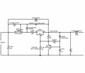
See schematic attached of what i am considering my final design and it is marked up as to the test setup. R4, R6, R7, and R8 are as shown on the schematic. No mods to your regulator other than shorting out R4.
For the test, i used a Hammond 382X transformer though (120/1000VCT 283VA) as that is what i had on hand at this stage. I reduced the primary voltage to 78Vac. With a resistor load of 2.8kohm on the output of the 390VDC regulator (139mA), the voltage at the Reg input was 421Vdc with about a 2 volt p-p ripple. The output with the 10uF capacitor on the Reg output was 390Vdc with ripple less than 1mV (ie my oscilloscope could not detect it considering the white noise that appeared at that sensitive a range.). Without the 10uF capacitor on the output, the result was very unstable and extremely vulnerable to my 'tap test' (you know, tapping the heat sink with a pen); it would create a very large ripple on the output and would take time to settle.
Operating the SEL KT88 amplifier, the load was 98mA (cheep Chineeze tube for test purposes; the NOS Marconi which will be in the final product draws 120mA when the amp circuit was checked) and again the ripple non existent. Hum on the output though. Grounded the heater and the hum disappeared. Remember, this is a bread boarded amp and power supply right now with wires all over the place. Flourescent lights shut off when i take measurements.
Final comment on the filter capacitor; i replaced the two 800uF capacitors with two 80 uF capacitors. The ripple on the output of the regulator became 5mV p-p which is really not bad and i suspect inaudiable. This i will have to check using the amp as the load.
Attachments
One for thing, it appears that the 5VCT winding on the power transformer should be able to operate the op amp power supply. do you think a 5Vac supply to CON2 would be reliable. it would save one more transformer in the final design. this would also mean the op amp power supply would energize the same time as Vin on CON 3. comments?
A 5 V winding should work, though, I'd definitely verify that the 12 V zener diode (D8) in the regulator has enough current running through it. Perhaps reduce R9 to 180 ohm or so. Verify that the zener regulates even when the primary voltage is reduced to 90 % of the nominal mains voltage.
Depending on your load current and reservoir cap, the 700 VCT transformer may work. Typically, I find that I get somewhere around 1.25*Vrms rather than the theoretical sqrt(2)*Vrms on the reservoir cap as the conduction angle of the diodes isn't zero. So at 10 % low on the primary voltage, you'd get 0.9*1.25*350 = 394 V. This doesn't leave enough headroom for the regulator. If you drop the output voltage to 380 V, you'd have 14 V of headroom. Just enough... Provided that the 700 VCT winding doesn't droop under load, etc. etc. Diode drops neglected.
Aside from that I see no issue with your design.
~Tom
Nice looking regulator, Tom.
I came here to find a ready made PCB for an LM317 HT regulator with soft start. Nothing on the web it seems. I'm thinking of a design more or less straight from the data sheets like this.
Can anyone see anything wrong with it. It looks like it should even withstand a shorted output. Haven't tried it yet.
Regards,
Bob
Attachments
Nice looking regulator, Tom.
Can anyone see anything wrong with it. It looks like it should even withstand a shorted output. Haven't tried it yet.
Polarity of D3?
Value of R6?
regards
Thanks for the feedback.
Always get confused with these FET symbols (drain to right, source left) but SPICE agrees D3 is the right polarity. It doesn't really do anything except protect the gate when voltages get dizzy.
You're right, R6 is high. It just feeds the zener Z4 to make sure there's 15V between gate and output. Didn't want it getting warm on start up. 30K would be a better value.
If you have LT spice, the LM317 model can be found here;
How to use LM317 LTspice Model
Maybe it's from the tech. groups at Yahoo;
http://tech.groups.yahoo.com/group/LTspice/files/ Lib/
In case you don't wish to dig or mess around, I've zipped the files below, and included the .asc file. Don't know if that's sufficient for it to work.
View attachment LM317.zip
View attachment soft start 317 regulator.asc
Save symbol file as LM317.asy, in lib\sym\misc
Save model file as LM317.sub, in lib\sub
Regards,
Bob
Thanks for the feedback.
Always get confused with these FET symbols (drain to right, source left) but SPICE agrees D3 is the right polarity.
Yes, i was wrong. It is late and i need some sleep...
regards
I came here to find a ready made PCB for an LM317 HT regulator with soft start. Nothing on the web it seems. I'm thinking of a design more or less straight from the data sheets like this.
Can anyone see anything wrong with it. It looks like it should even withstand a shorted output. Haven't tried it yet.
With 200 V in and a beefy cascode, you may be able to get the regulator to survive an indefinite short circuit. But note that the "current limiter" of the Maida regulator is really ill-defined and soft. Basically, what happens is that the LM317 runs out of headroom as the voltage across the cascode and input resistance to the '317 gets too large for the '317 to maintain regulation.
I've learned that there are a few things to watch out for with these high voltage regulators.
1) They need to survive start-up.
2) They need to survive momentary connects/disconnects of the load.
3) They should regulate the output voltage and remove ripple.
That turns out to be a pretty tall order. I got 1) and 3) taken care of in my circuit and if you add an external cap on the output and perhaps a snubber across the pass device, you can nail 2) as well.
I'm currently out of stock on my regulator boards so I'm trying to decide where to go next. I may make another revision that has some of the suggestions for improvements I have received implemented on the board. But I'm also considering revisiting the Maida Regulator. It's a pretty rugged regulator and works quite well for low voltages, currents. It would be nice with a beefed up version.
~Tom
But I'm also considering revisiting the Maida Regulator. It's a pretty rugged regulator and works quite well for low voltages, currents. It would be nice with a beefed up version.
If you do go there, Tom, it would be useful to make a versatile generic Maida PCB which makes provision for;
1 A soft start pnp such as MPSA92 or higher voltage equivalent. The nodes are already there in the Maida circuit. It just requires 3 extra holes. Simply don't use them if soft start isn't wanted.
2 A current limiting resistor before the 317 input.
3 AC input, i.e. full wave input rectifier diodes with optional series resistors to provide the low noise equivalent of a valve rectifier. This followed by a beefy smoothing capacitor.
4 Two optional RC output filters such that outputs can be directly wired to a valve amp or to each channel of a preamp.
I'd buy a couple of them to help spread the cost. I'm thinking of this, perhaps with other optional add-ons;
Attachments
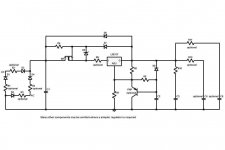
Actually, R6 in the previous circuit is redundant and D5 should have been connected directly to gate anyway, so I've removed it and re-named the resistors.
Enough for now. It's best that I build and test the circuit to see if it's worth pursuing any further. I'll order parts tomorrow and, hopefully, report my findings over the weekend. I'll monitor;
The soft start performance.
Rapid on/off switching from a power supply.
The effect of stroking the load lead against the output terminal.
Crowbarring the output (with optional RC filters disconnected).
Bob
Attachments
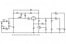
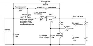
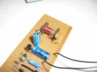
I built the prototype today and tested it without a load. The attached images show the prototype and the actual component types and values used.
It appears to work well. The soft start behaves very much like a valve rectifier, gradually increasing output voltage (over about 10 seconds with values shown). It isn't a linear ramp as would be the case with a P channel MOSFET since the pnp base draws a little current, and the timing resistor value needed to be approximately halved to get a similar time constant. LTSPICE predicts this.
It gracefully changes voltage state on repeated switch-on/switch-off of the unregulated (but smoothed) DC supply used.
Enough for today. Tomorrow, I'll try and destroy it.
Regards,
Bob
Attachments

I probably wouldn't include the input rectifier and reservoir cap. Those are very application dependent. The reservoir cap is also huge - in my setup at least half the board area if not more would be reservoir cap. So including those caps would basically double the board cost. These components are easy to place elsewhere in the chassis and easy to mount on a piece of vector/vero board.
I hope you're not in a rush. Nothing around here seems to happen in a hurry... Between work (you know what pays my parts budget 🙂) and hockey, there isn't much time for regulator development. That said, I've been known to suddenly get the bug and get stuff cranked out. Stay tuned.
My main challenge is that I need a regulator that'll provide 470 V, 200 mA without blowing up when loaded by a capacitive load. Accounting for mains variation, this means upward of 600 V in... Lots of energy to blow stuff up.
~Tom
I've zipped and attached MPSA92.sub from the data provided in the Fairchild datasheet to paste into /lib/sub, though it might have been captured in the attached .asc files. Let me know if it's redundant.
The simulation shows that switching a 10K load in and out causes no problem and this was then confirmed with the prototype by stroking a 10K load terminal against the output. From this, it can be concluded that loose valve connections in a preamp wouldn't destroy the regulator.
However, the simulation predicts that shorting the output places extremely high current spikes through the protection diodes and zeners. To simulate, change R_load to 0.001 ohm. A practical test obviously wasn't carried out. This doesn't question the requirement for a current limiting resistor in the design because this is a crowbar scenario.
The workaround is to use an RC filter at the output as previously suggested as being optional in my earlier recommendations for a PCB layout. Obviously, an RC filter is mandatory if shorts are expected or where the quiescent current is high and interrupted by loose valve connections. In this example, with R_filter = 20R and C_filter = 100uF, current surges in the diodes and zeners are negligible when the output is shorted. An RC filter with f-3dB of around 100Hz would be a good design choice. A practical test with RC filter in place wasn't performed for obvious reasons.
I've attached another .asc file to simulate input switching. Normally, with the required smoothing capacitors providing a slow voltage ramp up, current surges through the protection diodes and zeners are negligible. This example shows what would happen if the time constant was ridiculously and impractically small. I only include it to demonstrate that contact breaking (unlike making) causes no problem.
In summary, a successful exercise and quite suitable for a preamp power supply, so I'll leave it there and let Tom adapt it for use in power amps.
... and I still haven't got the PCB I came here for.
Anyone else interested in making a soft start preamp PCB to my previous specification?
I've designed what promises to be a really good DAC amp and I'm keen to build it - two stage feedback design using ECC88, critically damped HF with subsidiary DC feedback. All capacitors inside the feedback loop. I'll post on a separate thread if it ever gets built.
Bob
The simulation shows that switching a 10K load in and out causes no problem and this was then confirmed with the prototype by stroking a 10K load terminal against the output. From this, it can be concluded that loose valve connections in a preamp wouldn't destroy the regulator.
However, the simulation predicts that shorting the output places extremely high current spikes through the protection diodes and zeners. To simulate, change R_load to 0.001 ohm. A practical test obviously wasn't carried out. This doesn't question the requirement for a current limiting resistor in the design because this is a crowbar scenario.
The workaround is to use an RC filter at the output as previously suggested as being optional in my earlier recommendations for a PCB layout. Obviously, an RC filter is mandatory if shorts are expected or where the quiescent current is high and interrupted by loose valve connections. In this example, with R_filter = 20R and C_filter = 100uF, current surges in the diodes and zeners are negligible when the output is shorted. An RC filter with f-3dB of around 100Hz would be a good design choice. A practical test with RC filter in place wasn't performed for obvious reasons.
I've attached another .asc file to simulate input switching. Normally, with the required smoothing capacitors providing a slow voltage ramp up, current surges through the protection diodes and zeners are negligible. This example shows what would happen if the time constant was ridiculously and impractically small. I only include it to demonstrate that contact breaking (unlike making) causes no problem.
In summary, a successful exercise and quite suitable for a preamp power supply, so I'll leave it there and let Tom adapt it for use in power amps.
... and I still haven't got the PCB I came here for.
Input rectifiers and a smoothing capacitor could be included on a preamp PCB, Tom.I probably wouldn't include the input rectifier and reservoir cap. Those are very application dependent. The reservoir cap is also huge - in my setup at least half the board area if not more would be reservoir cap. So including those caps would basically double the board cost. These components are easy to place elsewhere in the chassis and easy to mount on a piece of vector/vero board.
Anyone else interested in making a soft start preamp PCB to my previous specification?
I've designed what promises to be a really good DAC amp and I'm keen to build it - two stage feedback design using ECC88, critically damped HF with subsidiary DC feedback. All capacitors inside the feedback loop. I'll post on a separate thread if it ever gets built.
Bob
Attachments
I've just re-read my last post and my conclusions were inadequate and one statement was wrong so I thought I'd correct that before I leave it.
I attached the files in the wrong order which may cause confusion. The switched input .asc file should have been attached last, rather than first. This scenario is unlikely unless there are bad contacts after the smoothing capacitors, or if input connections are flashed onto a live DC power supply. The point here was that an abnormally abrupt making, rather than breaking, of the circuit was the problem.
The soft start power supply with the protection devices shown is fairly bullet proof under normal conditions. The main problem is an unlikely short circuit as shown in the second attachment (which should have appeared first).
The above statement I made is wrong. An open output circuit doesn't appear to be an issue. Neither does re-closing the circuit with the correct design load. This being the case, loose valve base connections wouldn't be an issue.
In the shorted output scenario, it seems that the quiescent current is largely irrelevant, whether it be for a preamp or a power amp. The high current surges through the protection diodes and zeners are a direct result of the LM317 output being rapidly pulled down by the short causing capacitors to discharge through them. An RC filter on the output would slow this process as seen up front which would probably protect the components, although it might damage the capacitor. A foldback current limiting circuit instead of the current limiting resistor, as suggested by Tom and others, can also eliminate the problem.
Irrespective of the quiescent current, where the output is not rapidly pulled below it's normal regulating voltage, there wouldn't be damaging high current surges through the protection diodes and zeners.
I hope this clarifies and corrects. Sorry for any confusion.
I attached the files in the wrong order which may cause confusion. The switched input .asc file should have been attached last, rather than first. This scenario is unlikely unless there are bad contacts after the smoothing capacitors, or if input connections are flashed onto a live DC power supply. The point here was that an abnormally abrupt making, rather than breaking, of the circuit was the problem.
The soft start power supply with the protection devices shown is fairly bullet proof under normal conditions. The main problem is an unlikely short circuit as shown in the second attachment (which should have appeared first).
... or where the quiescent current is high and interrupted by loose valve connections.
The above statement I made is wrong. An open output circuit doesn't appear to be an issue. Neither does re-closing the circuit with the correct design load. This being the case, loose valve base connections wouldn't be an issue.
In the shorted output scenario, it seems that the quiescent current is largely irrelevant, whether it be for a preamp or a power amp. The high current surges through the protection diodes and zeners are a direct result of the LM317 output being rapidly pulled down by the short causing capacitors to discharge through them. An RC filter on the output would slow this process as seen up front which would probably protect the components, although it might damage the capacitor. A foldback current limiting circuit instead of the current limiting resistor, as suggested by Tom and others, can also eliminate the problem.
Irrespective of the quiescent current, where the output is not rapidly pulled below it's normal regulating voltage, there wouldn't be damaging high current surges through the protection diodes and zeners.
I hope this clarifies and corrects. Sorry for any confusion.
I started to look at ways of bringing the regulator output line down gracefully in the event of a short circuit to prevent the predicted high current surges through protection diodes and zeners.
My simplest idea was to use an inductor, and LTSPICE showed that 50uH was sufficient (reactance 3.14 Kohms at 10MHz), the DC resistance not being too important. Eager to try it out, I robbed one from a scrap valve oscilloscope and soldered it to the output of the prototype I'd made.
I removed the 2.7R resistor in series with the 1uF capacitor from the prototype since it typically represents the electrolytic capacitor's series resistance anyway, and I set all capacitor series resistances to 3R in the LTSPICE model.
The model predicted a surge of 17A during a short so I switched the prototype on and braced myself for a good spark. It was disappointingly small. Many repeated shorts were carried out at different times during the voltage ramp without damaging effect.
An RC filter typically comprising 22R and 100uF could be placed before or after the choke, according to SPICE, or an (R+L)C filter could be used.
It's interesting that the circuit diagram for the scrapped oscilloscope shows that these variable 50uH inductors were used in series with 4.3K or 3.9K load resistors in ECC88 differential amplifiers and tuned to produce optimum square wave response. That noted, the protection inductance could be used to enhance the performance of the amplifier in many designs.
So there it is. A high voltage soft start regulator, tolerant to shorts and now looking very bullet proof.
Attachments
- Status
- Not open for further replies.
- Home
- Amplifiers
- Power Supplies
- High Voltage Regulators (Maida or zener)