At #67, you listed 9610. At #68, I merely picked it from your list.
I would assume you knew it was P, and to flip the circuit for P???
Nothing to panic about, I doubt you have blown anything up...
Yeah, just reverse the cap and power connections.
Layout looks fine. Though I can't see the back to be sure.
Except R5 almost certainly wants to be adjustible,
and R7 might benefit from adjustability too.
Last edited:
Are you going with -24V at the top, and GND at the bottom?
Or GND at the top, and +24V at the bottom? Whichever end
you choose as ground, C12 should probably go there too. It
may affect PSRR.
-------------
On second thought, no. Leave C12 where it is. Flip it if you
have to change polarity. But don't change where it connects...
Or GND at the top, and +24V at the bottom? Whichever end
you choose as ground, C12 should probably go there too. It
may affect PSRR.
-------------
On second thought, no. Leave C12 where it is. Flip it if you
have to change polarity. But don't change where it connects...
Last edited:
Are you going with -24V at the top, and GND at the bottom?
Or GND at the top, and +24V at the bottom? Whichever end
you choose as ground, C12 should probably go there too. It
may affect PSRR.
-------------
On second thought, no. Leave C12 where it is. Flip it if you
have to change polarity. But don't change where it connects...
Thanks man!
As far as power goes, I was thinking v+ at the source of M3 and v- at the drain of M1. Well, I hope that's right.
Though it probably has enough open loop gain for decent gain balance.
What guarantees the midpoint of the 100K's is GND and doesn't drift?
I'm thinking this will have DC offsets that don't match.
Oh, nevermind.. That GND drift won't matter, I just spotted the 10uF in
the feedback loop. DC can match as well as the output JFET pairs match.
And drift with temperature in unison... Its OK. A lot of parts though...
Thanks man!
As far as power goes, I was thinking v+ at the source of M3 and v- at the drain of M1. Well, I hope that's right.
If M3 source rail isn't GND, it will become sensitive to supply ripple there.
No big deal if really clean and/or well bypassed. But the entire circuit was
designed for single rail, and all reference to M3's source not easy to undo.
Earlier, I thought maybe you could just move C12 to wherever the new GND
was, but that doesn't fix the real problem. The output center is a multiple
of M3's VGS, and always referenced to M3's source. When GND is there, it
presents no problem. If GND is moved somewhere else, causes poor PSRR.
For P-CH, Best GND at the source of M3 and -24V at the drain of M1.
Last edited:
If M3 source rail isn't GND, it will become sensitive to supply ripple there.
No big deal if really clean and/or well bypassed. But the entire circuit was
designed for single rail, and all reference to M3's source not easy to undo.
Earlier, I thought maybe you could just move C12 to wherever the new GND
was, but that doesn't fix the real problem. The output center is a multiple
of M3's VGS, and always referenced to M3's source. When GND is there, it
presents no problem. If GND is moved somewhere else, causes poor PSRR.
For P-CH, Best GND at the source of M3 and -24V at the drain of M1.
I have a transformer and a positive regulator. The fact that it is a positive regulator doesn't really help me find a ground, since the circuit is a single rail and since the power transformer isolates. This outputs V+ and V- and if it should happen to be outputting a ground, I do not know it.
The power circuit is supposed to be as close as possible to a battery and I do not know how to find the ground of a battery. 😕 One end is positive and the other end is negative.
I found the ground! When I plug in the computer source, it will send earth ground to shield of the RCA jack. There is the ground.
I assume by ground that you mean to connect small signal ground from the computer to the source of M3 and the small signal 0v line of the power amp. Is that correct or only half correct?
Its OK. A lot of parts though...
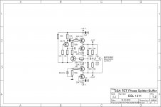
That is very serious version with four fets acting as buffers, assuming to get perfect drive for the next stage.

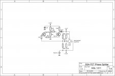
Here's one for the minimalist person hoping impedance match will somehow come along ...

Attachments
Both are interesting. I can't wait to see what the next looks like.That [post 84] is a very serious version with four fets acting as buffers, assuming to get perfect drive for the next stage.
Here's [post 88] one for the minimalist person hoping impedance match will somehow come along ...
P.S. Most computer sound cards would like to drive 10k.
Ken? Power circuit example?
Ken, rather than me guessing a power circuit, would you do me the favor of posting a readily doable power circuit (or link to same) that you would like to see used with your phase inverter?
For this phase inverter, a large portion of its effectiveness for audio is not on the schematic, since a voltage is only as important as its reference, and the absent power circuit is the reference for all of the AC signal. With the layout as an example, apparently, I can guess well, and it was a huge surprise. But surprise at the power circuit doesn't seem appropriate, as it just might be powered by a combination of my confusion and a transformer. I would prefer to reduce guesswork when possible.
Thanks!!
You need GND (must be GND at bottom) and -24 (at the top).
I dunno, any cheap switchwort located far away will probably do.
Slide big common mode choke bead over the cable somewheres.
And a bypass cap near the circuit board. No big deal.
I think it much easier to filter trash off a high frequency switcher,
than try to filter 120Hz ripple from a non-switcher... Either way,
you get the DC isolation you need to choose either end as GND.
OK if the high side of the wort is grounded to the wall, but the
24V side should be floating. Would be the normal case anyways...
If there's a ground lug on the wort, I'd check with an ohmmeter
just to be sure the side we care about floats.
Last edited:
I've found that transformer bandwidth can be extended by
deliberately mismatching the input and output impedance...
.
he's right about this--i use edcor $13 traffos this way and if you keep dc off them and use them way below their power ratings it works out incredibly well. ex: really cheap way to build a sweet 6922 (tube) headphone amp
Of course there is the old BOSOZ just ground one input to have a phase spliter.
http://www.diyaudio.com/forums/pass-labs/17560-bosoz.html
http://www.diyaudio.com/forums/pass-labs/17560-bosoz.html
Of course there is the old BOSOZ just ground one input to have a phase spliter.
http://www.diyaudio.com/forums/pass-labs/17560-bosoz.html
yes, it's a nice solution indeed with a very reasonable BOM .
yet if i value my time at any reasonable rate, or if the supply is not already split-rail or heat and/or power budgets are at their limit, the edcor traffo costs less in the end.
but then, of course, in a high EMI environment or with DC on it, the $13 traffo would not work so well and BOZOS would beat it.
Not everyone here is smart as you are, but we are trying and learning ... 😉
Here is simple but effective solution with all possible options at the input as well as on the output, buffers already included to drive power amp for each phase.
Regards, Andrej 🙂
Hello, is there a way to use this circuit without a input transformer? I mean using it with a rca input . I will try to use this circuit with one mono signal input in order to have 0° and 180° output phase .
Thank you..
Its called a phase-splitter as it generates in-phase and anti-phase. The name is in use hard to change it now!
Hello, yes i know the splitter. I had try to simulate this but i need to know how manage the input signal without transformer. So how to connect the input and output ground.
This one uses BJT's but could probably be adapted to use FETs.
Making balanced output from single end
Making balanced output from single end
This one uses BJT's but could probably be adapted to use FETs.
Making balanced output from single end
Hello, thank for the suggestione, i will take a look. What do you think about my attached file? It is more simple but seem to work on sym. Thanks.
Attachments

- Home
- Amplifiers
- Solid State
- Fet based phase splitter?