As per my comments above, the Over and Under Voltage protection Zeners also have to change(Z100,Z101) if you want to run the board at lower voltages. 😉
Temporarily, I don't have IRFI4212H.
But, L15D can use lower voltage, modify the resistance data .😀
How about balanced connection? Can they natively work with xlr connections?
I think this one: Class D Audio SDS-224 Amplifier - Class D Audio Amplifiers - PRODUCTS
Is based on the irs2092 (but much more expensive 😀). It has a good balanced support.
I really hope to see a L10D version with 60w, without need to change anyting 😉
The SDS-224 must be using some balanced to unbalanced converter onboard, since the irs2092 input is unbalanced...
Temporarily, I don't have IRFI4212H.
But, L15D can use lower voltage, modify the resistance data .😀
Too complicated for me who don't know anything about diy 😀. I will wait hoping that in the future the l10d will become commercially available 😀
As per my comments above, the Over and Under Voltage protection Zeners also have to change(Z100,Z101) if you want to run the board at lower voltages. 😉
B: yes. It is to point to IRAUDAMP7S. For example, I make L15DX2.
But not including L15D. It does not limit the voltage regulator.
Too complicated for me who don't know anything about diy 😀. I will wait hoping that in the future the l10d will become commercially available 😀
This is not complicated. I often such modified to work of low voltage.
Maybe I'll consider soon after to L10D of. How much do you think DC POWER is more convenient
The issue is that when one wants to build a multi-channel amp, voltage requirements do not change, but amperage requirements can go up drastically. This is not a big deal if using a linear supply, but a SMPS does not have the same flexibility.This is not complicated. I often such modified to work of low voltage.
Maybe I'll consider soon after to L10D of. How much do you think DC POWER is more convenient
For example, I want to build an 8-channel amp, and I have calculated my DC requirements to be +/- 40V, but the total peak current draw will be in the neighborhood of 16 amps. For a given power level, you can get more amps if the voltage of the SMPS is lower, and therefore you don't have to buy more power supply than you need.
The issue is that when one wants to build a multi-channel amp, voltage requirements do not change, but amperage requirements can go up drastically. This is not a big deal if using a linear supply, but a SMPS does not have the same flexibility.
For example, I want to build an 8-channel amp, and I have calculated my DC requirements to be +/- 40V, but the total peak current draw will be in the neighborhood of 16 amps. For a given power level, you can get more amps if the voltage of the SMPS is lower, and therefore you don't have to buy more power supply than you need.
I like L15D himself. Even spent more time to modify its performance.
It works in DC +-50 V is for most of the power supply requirements,
And the output power of the sound box needs.
I think the CLASS D is the advantage of efficiency, relative simulation for power amplifier, big power some advantages are more obvious.
I don't like the small power CLASS D, CLASS T. 10 to 30 watts of power I prefer to use
LM4766T.

ljm_ljm,
With the heat sink vertical on the board it doesn't look like convective airflow over the fins will be very good, since the board underneath blocks it.
Do you know what is the maximum average power that a module can dissipate when in a closed box?
And how much if the box has ventilation holes above the heat sink?
Also , what are the dimensions of the board? I searched but didn't find them, and the ebay vendors don't give them either.
Thanks
The dimensions are on the board layout diagram in most of the ebay ads (see the edges..) its about 131MM x 57 MM
Ah, so it is, thanks.
Two out of three ain't bad; what's the height? 🙂
Is there a minimum space between adjacent boards and the amp modules and the PS?
Trying to figure out what size case is needed.
Two out of three ain't bad; what's the height? 🙂
Is there a minimum space between adjacent boards and the amp modules and the PS?
Trying to figure out what size case is needed.
Ah, so it is, thanks.
Two out of three ain't bad; what's the height? 🙂
Is there a minimum space between adjacent boards and the amp modules and the PS?
Trying to figure out what size case is needed.
I'm interested too, there are 2 cases found on ebay for power amp. One is large about 185mm, and it is large enough, but too large for the space I have. I can only use the 165mm one, and dunno if that is big enough.
ljm_ljm,
With the heat sink vertical on the board it doesn't look like convective airflow over the fins will be very good, since the board underneath blocks it.
Do you know what is the maximum average power that a module can dissipate when in a closed box?
And how much if the box has ventilation holes above the heat sink?
Also , what are the dimensions of the board? I searched but didn't find them, and the ebay vendors don't give them either.
Thanks
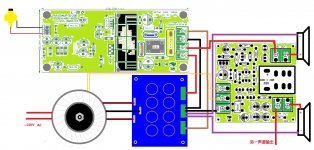
I send connection diagram in front have a mark on size.
The radiator height about 40 MM. Plus installation about 5 MM copper column。
L15D can use 30 MM height of the radiator. If be necessary, can indicate
Attachments

The radiator height about 40 MM. Plus installation about 5 MM copper column。
Thanks!
Cyan,
I've been searching for cases too, here are some other sources:
Audio Catalog
thlaudio web site pages
eBay - New & used electronics, cars, apparel, collectibles, sporting goods & more at low prices
Hi-Fi 2000 contenitori per l'elettronica, case modding HTPC, Galaxy, rack, DIYaudio, computer cases, front panel express, knobs,milled Handles, milled fronts, hi-end,
modushop.biz
Par-Metal
General protector
This and all of the other speaker protector boards on ebay say that they require AC.
I expect they work with DC also, but is there any issue with doing that?
The SMPS I will use has only 12 VDC auxiliary voltage.
This and all of the other speaker protector boards on ebay say that they require AC.
I expect they work with DC also, but is there any issue with doing that?
The SMPS I will use has only 12 VDC auxiliary voltage.
No problem, but need to make some changes.
Will the DC12V + and-in the direct connection LM7812 can work OUT GND.
Will the DC12V + and-in the direct connection LM7812 can work OUT GND.
Sorry, I don't understand.
But if it helps, the PS has both + and - 12V outputs.
If you are talking about this one: http://www.ebay.com/itm/110620807058?ssPageName=STRK:MEWAX:IT&_trksid=p3984.m1438.l2649, you could remove the 7812 regulator, and run the +12 directly in to the printed circuit hole where it's output pin was. and the ground from the power supply would go on the regular ground point.. It would probably be a good idea to get a schematic for it as well. If you had the schematic, you could pull out the first component after the ac input connector so that the rest of the circuit was out of the way, and use AC12 as the input point (to keep it clean, and then run a wire from there to the (former) output of the 7812..
Last edited:
Be careful what you do with the 12 volts to the 2092. It can be a bit touchy about decoupling close to the regulator and close to the 2092.
I didnt decouple mine well enough and I started getting clicking through the audio.
Turned out to be glitches on the VCC 12 volt rail.
I didnt decouple mine well enough and I started getting clicking through the audio.
Turned out to be glitches on the VCC 12 volt rail.
- Home
- Vendor's Bazaar
- LJM Audio