I'm interested in purchasing the L15D or L20D from one of these sellers but wanted to contact along1986090 before hand but could not find any contact info. ljm_ljm or anybody else have their details?
On the Item description tab, scroll down to the bottom and under "Questions and Answers" click the "ask a question" link.. skip the canned Q and A and select "other" and then you can ask any question you want.
Does anyone know how tall this heatsink is (the stereo board)? I didn't factor that in. I have a 4" tall case.
The dimensions are given in the listing, or maybe the other guy's who sells them.
On the Item description tab, scroll down to the bottom and under "Questions and Answers" click the "ask a question" link.. skip the canned Q and A and select "other" and then you can ask any question you want.
Excellent! I was on that page but could not find that option before. Thanks.
7G17
@ ljm_ljm:
Yesterday I soldered my L15Ds. Testet just that they run, not yet real power.
I like those ferrites, that you use. Where can I get them?
I'd like to use them for the Iraudamp7S, that I buit before.
There I used iron powder toroids.
I was not (yet) able to get the coils from the IR parts list (sagami or Ice)
here in Germany.
cheers
If you need this kind of inductor. You can contact the dealer. I can provide here a lot.
hey ljm_ljm,
I'm about to order some L15D modules and was wondering what speaker protection board I should order with it. I noticed the PCB silkscreen on the speaker protector board you built for a friend had your alias on the silk screen. Did you design a speaker protection board and what voltage does it take. I'm looking to use a special and rather expensive SMPS from audiopower.it
It's called the DPS-500/S-D It's secondaries are 2 rails +/-22V in the 200mA range. It also has +/- 12-15V that's LM347 regulated. I believe both are DC and I think the protection boards voltage is for AC looking at it's components.
I intend to drive 6 modules with that SMPS.
Any solution for those secondaries for a protection board?
I think ljm_ljm suggested This one earlier on this thread, or another one. It would be pretty easy to bypass the regulator etc on the board and feed it 12 V DC directly from your SMPS.
Thank you for your reply.
This protection circuit can really use. If you use the DC 12V power. So please + -, access 7812's, PIN3, PIN2.
7812 can not install.
In addition,
Protection board can buy a separate transformer, EI shape. 5VA. AC12V. It is very cheap.
ljm_ljm, thanks for your design!
I have ordered a stereo kit, but i wonder whether i'll be able to use it with 2.66ohm loads, at +-48V regulated SMPS?
The SMPS i use has current limit set on 650W (6.7A into each power rail), plus IRS2092 has it's own current limit, plus i'll have current/voltage gauges to control the power draw.
Single SMPS for a pair of boards.
Thanks!
This protection circuit can really use.
Can you please list the protection features of this circuit?
Delay/slow start?
DC offset protection?
How about output short circuit (crowbar) protection?
Thanks!
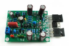
L7 MOSFET AMP
I designed a small power amplifier。
It uses a pair of VISHAY IRFP240 IRFP9240。
It uses the CFP input, and the suspension of the output, similar to LME49830 structure.
It works in very stable.
In the +-56V voltage.it is can out 150W 8R。
PCB board area 63*78MM only
I designed a small power amplifier。
It uses a pair of VISHAY IRFP240 IRFP9240。
It uses the CFP input, and the suspension of the output, similar to LME49830 structure.
It works in very stable.
In the +-56V voltage.it is can out 150W 8R。
PCB board area 63*78MM only
Attachments
Any chance for schematic now?
It is pointless to make such threads without schematics and only one or two pictures. If this is a commercial product and you don't want to share it only to show the beautiful PCB (actually is very beautiful!) there is a thread for pictures and it will be better to post more of them.
I'm very curious about the schematic because I'm IRF lover so if there is any chance to see it will be very happy.
Best regards!
Last edited:
Do not worry.
This circuit can be a good power play IRF FET.
I can briefly explain.
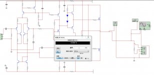
It uses the CFP transistor input stage. Single-ended voltage amplification.
Internal structure similar LME49830, suspension of driving.
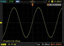
It can work very high frequency, and waveform perfect.
I tested with the 2700K HZ.
Does not appear as an ordinary FET amplifier instability phenomenon.
This circuit can be a good power play IRF FET.
I can briefly explain.
It uses the CFP transistor input stage. Single-ended voltage amplification.
Internal structure similar LME49830, suspension of driving.
It can work very high frequency, and waveform perfect.
I tested with the 2700K HZ.
Does not appear as an ordinary FET amplifier instability phenomenon.
I will try to design better quality amplifier, and they are very cheap.
I would like to include not only an actual amplifier circuit, but also includes parts of the performance and parameters. I think this is a whole.
Will be used only truly understand.
I would like to include not only an actual amplifier circuit, but also includes parts of the performance and parameters. I think this is a whole.
Will be used only truly understand.
Hi
I see I'm not the only one that uses totem pole BJT driver stage for each output FET gate. I do prefer the totem pole driving stage always stays well within class A. Using simple diode bias may cause one of the devices to leave class A during very fast transient output current signals, also it requires thermal feedback to the diodes because without the degeneration of an emitter resistor, thermal runaway can destroy a small signal device in a few blinks of the eye. I use 3 diodes and an emitter resistor on the inside BJT to set bias above the largest charge current needed to operate the FET. Many semi-fab companies make triple diodes in a 6 pin SMD package.😉
I see I'm not the only one that uses totem pole BJT driver stage for each output FET gate. I do prefer the totem pole driving stage always stays well within class A. Using simple diode bias may cause one of the devices to leave class A during very fast transient output current signals, also it requires thermal feedback to the diodes because without the degeneration of an emitter resistor, thermal runaway can destroy a small signal device in a few blinks of the eye.
I use 3 diodes and an emitter resistor on the inside BJT to set bias above the largest charge current needed to operate the FET. Many semi-fab companies make triple diodes in a 6 pin SMD package.😉
Last edited:
Please post schematic and pcb layout as many diy enthusiasts will like to build the same. Extremely professional pcb does not look diy product.
Hi
I see I'm not the only one that uses totem pole BJT driver stage for each output FET gate. I do prefer the totem pole driving stage always stays well within class A. Using simple diode bias may cause one of the devices to leave class A during very fast transient output current signals, also it requires thermal feedback to the diodes because without the degeneration of an emitter resistor, thermal runaway can destroy a small signal device in a few blinks of the eye.
I am using IRF610 as the bias voltage provided. And with the output stage FET to maintain the same temperature.
Please post schematic and pcb layout as many diy enthusiasts will like to build the same. Extremely professional pcb does not look diy product.
If you have a L7. You will find the above parameters in detail. L7 is a very simple DIY AMP.
I am using IRF610 as the bias voltage provided. And with the output stage FET to maintain the same temperature.
Hi
My comments is in reference to the TO-92 driver stage(s), the undegenerated comp class A BJTs that are detached from the diodes that bias them, not the Vgs multiplier bias control for the FETs.
- Home
- Vendor's Bazaar
- LJM Audio