That's what I was wondering when I saw this mod. Let us know what happens.
Trouble is breaking the pin is a one-way street. Then again I have a spare so to heck with it - fingers crossed this'll cure it.
- J
Well got rid of that pin, and I still got pops on the SPDIF input.
Worse I now have horrible distortion on the Optical input with both nothing playing, or music playing.
I must have either heat-damaged that receiver chip, or it just didn't like being run with the 75R/0.01uF input configuration (unlikely as this is recommended in the Crystal datasheet I posted on the previous page).
Thankfully I had a spare receiver chip. This one was red, and the pinouts looked different to the existing black one I had. Took a chance (what the hell - it was still from Gigaworks!) and thankfully all working normally again TOUCH WOOD.
Won't try that mod again in a hurry 😉
- John
P.S. Thank I'm going to have to invest in a new board at this rate as I can see the day arise when some mod releases the dreaded magic smoke!
EDIT: wander if I should completely break the pin/leg to the daughter board, just incase there's any reflections or something coming from being still connected via the pins to the original circuit (output end of the SPDIF input transformer).
I wanted to suggest the same thing when I saw your first post with the photo....the leftover copper circuitry will affect the impedance.... also, you have used Cirrus drawing and applied in principal what they suggest, but omitted the section that talks about the capacitor choice: SMD device with X7R dielectric...the cap you use may have its (nice) sound signature, but it is NOT designed for S/PDIF coupling and will induce huge amount of jitter....
Boky
Last edited:
Sheldon, have you made any more boards? I'm sure there are a few of us that would like to try it, including me.
I didn't get much response with my call for interest in circuit boards, so I shelved the concept of doing a professional board run.
I've just purchased a couple of ICEPower amps, and if they sounds good, I may build up a DAC/attenuator/AMP in one chassis.
So I'll get working on a professional board run.
Sheldon
I wanted to suggest the same thing when I saw your first post with the photo....the leftover copper circuitry will affect the impedance.... also, you have used Cirrus drawing and applied in principal what they suggest, but omitted the section that talks about the capacitor choice: SMD device with X7R dielectric...the cap you use may have its (nice) sound signature, but it is NOT designed for S/PDIF coupling and will induce huge amount of jitter....
Boky
Ahhh you live and learn - thanks for that! That would definitely explain it 😱
Anybody want to check out my latest design before I drop it into the board shop?
Here's the layout:
http://quadesl.com/diyaudio/Final Artwork Prints.pdf
Here's the schematic:
http://quadesl.com/diyaudio/Schematic Prints.pdf
Here's the prototype pics and such:
Sheldon’s World Blog Archive Another Audio Digital-to-Analog (DAC) is Born
Suggestions are always welcome!
Sheldon
Here's the layout:
http://quadesl.com/diyaudio/Final Artwork Prints.pdf
Here's the schematic:
http://quadesl.com/diyaudio/Schematic Prints.pdf
Here's the prototype pics and such:
Sheldon’s World Blog Archive Another Audio Digital-to-Analog (DAC) is Born
Suggestions are always welcome!
Sheldon
Sheldon, I saw your post on the DAC a while back. Did you have any conclusions about the sound? How does it compare to the old tube unit? Did you compare it directly to the board this thread is about? Did you pick up any tips or tricks that might apply to people using the board here rather than rolling their own? Did you revise between the prototype and what you intend to have made? It's a nice looking bit of kit. I didn't spot any followup / conclusion post though.
Last edited:
Adam, I'm sure the Cirrus sound is still intact, but eliminating a lot of the compromises on the Chinese board has to help everything. Personally, I think the upsampling and the trafo coupling compliment each other greatly, but everyone has their own opinions. All the little mods people have done are so minor that most are probably not worth the effort, but using your own parts choices to build a board is the best opportunity to try lots of things.
Best, Bill
Best, Bill
I'd definitely like to purchase a board should there be a set manufactured, though I'd have to get someone to solder in the SMT chips I guess (tried it once - never again!).
I'll gladly sell them to people if people want.
I have the gigawork DAC that I bought after I drew up my design, but before I etched the board. My gigawork DAC has several analog stage mods:
Bypassed all coupling caps
Removed buffer stage
OPA627 opamps on carriers
Proper voltage on ASRC chip board.
My DAC sounds better, and I strongly suspect that 90% of the difference is the transformer vs. opamp analog stage. The signals are a lot cleaner on my board with the chips down near the groundplane vs up on dip carriers.
I'd like to get an idea of how many boards to buy in my board order, so if people want one let me know (stokes@quadesl.com).
As far as soldering on the main chips, it was a total PITA on my prototype board because I didn't have a solder mask and the pins wanted to fall between the copper fingers (forming a zipper type effect). I'm hoping with the solder mask that this is less of an issue.
However, if someone wants to buy a board, and the chips, I can solder the three main chips in place for you, but I'll have no way of testing them afterwards.
Sheldon
Any thoughts on the suitability of these transformers
Vintage Tamura PM2000 Output Transformer API Jensen | eBay
Vintage Tamura PM2000 Output Transformer API Jensen | eBay
Definitely suitable, and worth the money if you don't get gouged on shipping.
I have a pair out of a Yammy board and they are damned near as good as the Jensen JT-11DMs.
Best, Bill
I have a pair out of a Yammy board and they are damned near as good as the Jensen JT-11DMs.
Best, Bill
Thanks, I just bought 2. Shipping to Australia was US$20 which isn't bad. Strong Aussie dollar gives an even better deal. Total for the 2 tx's shipped is AU$66.
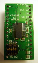
my CS4398 adapter PCB’s came in
A follow-up, my CS4398 adapter PCB’s came in. The original on the Ebay big DAC board is a poor design and with mine near death after rework lifting traces, I laid out a new board.
I wanted low impedance traces and nearby SMT decoupling caps for the CS4398- there’s no other way to meet the demands on the VREF pin (6ns/80mA spikes).
I succeeded in getting 1mVpp noise on the analog power pins and about 4mVpp on digital power pins. I kept the split grounds and there’s 5mVpp noise between them. I find huge improvements to detail, imaging and rhythm when there is decent (local) filtering of the rails and have to say the CS4398 can sound pretty damn good. But you have to do heavy mods to this board and it can’t take a lot of soldering/rework 🙁
The PCB was $5, CS4398 $13, caps/dipswitch/pins about $7, so it cost ahem 1/4 the price of the DAC I have a few spare blank pcb's if anyone wants.
A follow-up, my CS4398 adapter PCB’s came in. The original on the Ebay big DAC board is a poor design and with mine near death after rework lifting traces, I laid out a new board.
I wanted low impedance traces and nearby SMT decoupling caps for the CS4398- there’s no other way to meet the demands on the VREF pin (6ns/80mA spikes).
I succeeded in getting 1mVpp noise on the analog power pins and about 4mVpp on digital power pins. I kept the split grounds and there’s 5mVpp noise between them. I find huge improvements to detail, imaging and rhythm when there is decent (local) filtering of the rails and have to say the CS4398 can sound pretty damn good. But you have to do heavy mods to this board and it can’t take a lot of soldering/rework 🙁
The PCB was $5, CS4398 $13, caps/dipswitch/pins about $7, so it cost ahem 1/4 the price of the DAC
I have a few spare blank pcb's if anyone wants.Attachments
prairiemystic,
I would suggest to avoid any X7R, X5R, X8R, Y5V, Y5U, Z5U ceramic capacitor, especially in decoupling, as these are subject to the piezoelectric effect.
On one side you are killing high frequency noise and on other side you are increasing low frequency noise, which will affect jitter even harder.
You may use NP0/C0G ceramic capacitors or even better silver-mica.
Just try one single 1nF silver-mica across ASRC oscillator and you´ll immediately notice the benefits.
Regards,
Tibi
Last edited by a moderator:
That is funny, I would suggest strictly against silvered mica.... sound very harsh and don't do much to actually snub the noise from the supply pins to ground, mostly because they have leads....
My recipe is parallel combination of 100nF, 22nF and 1nF -> all X7R dielectric of at least 50V DC.... outstanding results... I also measure broad spectrum noise - the combination I suggested above snubs all noise at all frequencies (if the ground plane is of low-noise design). I can go from very clean, clinical, superbly defined sound at all frequencies (with excellent bass detail, definition and extension) to mellow / mushy sound (suitable for basic audio set-ups) just by applying the right amount and combination of SMD capacitors at all supply pins.
Boky
Last edited:
Silver-mica is also available in SMD.
Beside piezoelectric efect, X7R dielectric capacitors will suffer from capacity variation in direct relation with potential applied.
The link I posted earlier is a good article KEMET Electronics - Are your military ceramic capacitors subject to the piezoelectric effect?
Go for NP0 if you like ceramic sound.
Regards,
Tibi
- Home
- Source & Line
- Digital Line Level
- Experience with this DIY DAC ?