Alex_twn, your mods look really good. What is wrong with the sound? The main board grounding has a couple faults but not enough to make it sound poor.
I note your transformers are big, which means they have big magnetization currents and I'm not sure the 'lil 4398 can do well there.
I truly admire your modding attempts and your attention to detail, to correct some of the design flaws. Your comment about the trafos being physically too big, however, has no basis in fact. You should refrain from making speculative comments on subjects that you apparently don't understand. Bigger IS better. Better bass response, greater headroom, and lower distortion.
No disrespect intended, just being blunt, as I usually am.
Best, Bill
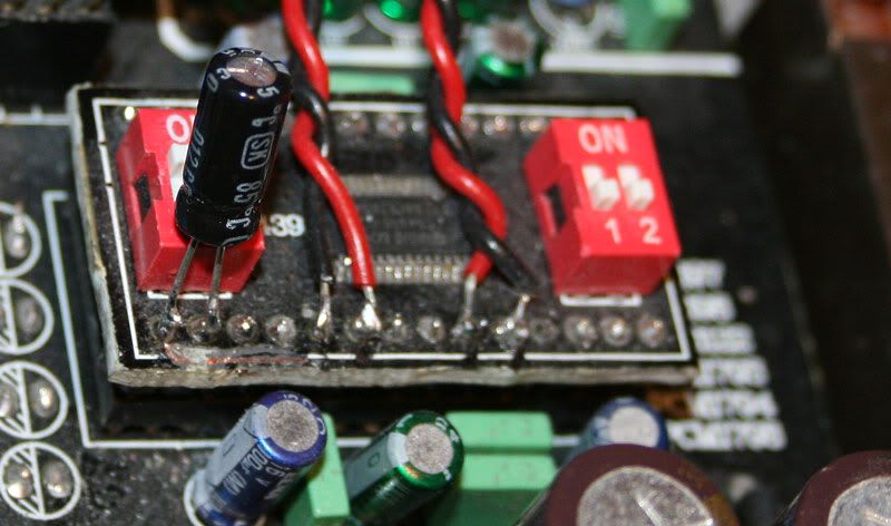
Once you maxed the mods in the abovementioned areas, AND if you wish to do so, you could use external oscillator clock for the resampler / upsampler plugin module, if you decide to use the upsampler module of course. This oscillator will need completely separate, very low noise power supply AND will have to be grounded to a point on the DAC PCB with lowest noise.
Good luck,
Boky
I did something similar following some advice from the guys on Pink Fish Media -
I removed the clock from the upsampling board & mounted it on a modified "Flea" low-powered regulator fed from its own power supply. This made a significant improvement but it's important to keep the new regulator away from other components as much as possible.
I'm using UTC A-20 transformers so I've space where the old op-amps etc. originally sat.
If you want to send 2.5v dc through along with the signal.
The 2.5Volts is on both sig+ and sig-, the transformer only cares about the differential voltage, not the offset from ground. That differential voltage is fractions of a mV.
My DIY 4398 DAC design has the DAC chip feeding the transformers through some smalish series resistors, no caps in sight. Works and measures like a champ.
Sheldon
Maybee you will get the same result if you feed the onboard XO with its ownI removed the clock from the upsampling board & mounted it on a modified "Flea" low-powered regulator fed from its own power supply. This made a significant improvement but it's important to keep the new regulator away from other components as much as possible.
regulator?
Edit:Where did you get the new XO?
Last edited:
I'm using UTC A-20 transformers so I've space where the old op-amps etc. originally sat.
Is that a LCR Polystyrene. Have you been testing Polypropylene before this with the traffo???
Where did you get the new XO?
It's the one i took from the upsampling board. Not an XO by the way.
Where can i buy this dac? What is the name. I have look at about 20 pages if this thread and not once, someone pronounce the name of the dac you are all talking about! Thanks
It's a generic Chinese dac, sold on Ebay for the most part. "upsampling 24/192 dac" would be the key search words. LM DAC is printed on the boards but there are many similar versions.
There have been several links posted in the last 10 or so pages of this thread.
Best, Bill
There have been several links posted in the last 10 or so pages of this thread.
Best, Bill
I did al littlte modding tonight..
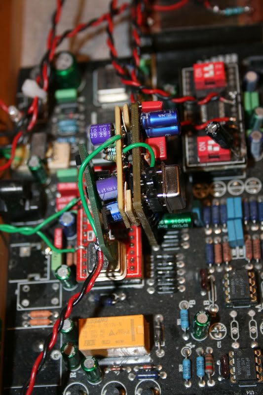
The Vref mod with the inductor:
And the trace and the e-lyt:
And I gave the oscillator on the upsampling module its own shunt regulator from Paul Hanes I had laying around:
I can´t swear that I hear any difference to the better,but on the other hand it doesn´t sound worse....😉
The Vref mod with the inductor:
And the trace and the e-lyt:
And I gave the oscillator on the upsampling module its own shunt regulator from Paul Hanes I had laying around:
I can´t swear that I hear any difference to the better,but on the other hand it doesn´t sound worse....😉
Hi sorry for my late answer here.
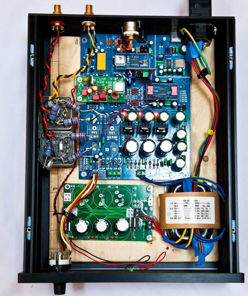
Those transformers were one the parts recommended on this thread long time ago, even if this is more the low end model from edcor, they are working with the DAC.
It is hard to see on the picture but I do have series resistors to adapt the impedance and match the DAC output requirements.
Thanks for your comments,
Well I remember to have done everything with some measurements before applying the mods.
First thing, looking at the schematics, I found out that the supply decoupling was not done as recommended in Cirrus data sheet so I decided to optimize the circuitry.
I tried to separate as much as possible power rails and analog / digital also separate the rails from each devices (i.e. 3.3V for DAC different than the one for the receiver with a common ground of course), I was able to do it by using the additional free LM317 on board.
Then I used some good parts (NPO / Nichicon MUSE) and yes I get better figures on the noise level but could I really hear something different from this mods? Not really actually.
I agree with you, the small DAC PCB is a multi purpose one and may sound better with 4397 even if I never try swapping the DAC.
I never went to external clock circuitry, I feel I am not going to get a huge improvement again here.
Transfo and PCB are grounded together, they are screwed on an aluminium plate together.
I agree with you for the controller, it can inject some noise here, but I also tried with no controller, actually the controller was the last mod when I was thinking to put all the system in a case and implement some nice control features like remote and display.
I don't have any capacitor, I just have the DAC output connected to the transformers through resistors.
I have been following this interesting subject here since the beginning I guess and implemented all the modifications recommended.
While some (transformers) gave a noticeable improvement, others gave close to nothing.
I feel that the PCB design + the modules on DIL sockets introduce some parasitic / noise that prevent to get the DAC best SNR, so improving the supplies don't really change something (in my case).
But I don't forget as well that this DAC is cheap and is a good value for the money spent + it is fun to try the mods (for some time only ... 😉).
Mine ended up in a drawer as I mentioned, because I decided to try a full balanced DIY DAC with dual DAC chip in mono mode and I got just after assembly a very good result, so I forgot a bit about the CS4398.
Alex.
Alex_twn, your mods look really good. What is wrong with the sound? The main board grounding has a couple faults but not enough to make it sound poor.
I note your transformers are big, which means they have big magnetization currents and I'm not sure the 'lil 4398 can do well there.
Those transformers were one the parts recommended on this thread long time ago, even if this is more the low end model from edcor, they are working with the DAC.
It is hard to see on the picture but I do have series resistors to adapt the impedance and match the DAC output requirements.
I have few suggestions:
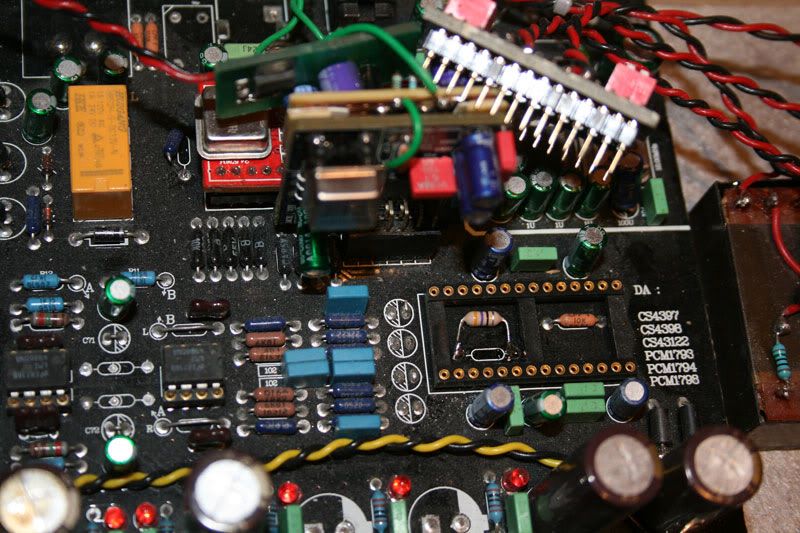
Instead of just randomly applying capacitors everywhere, it is better idea to actually measure the ground noise at various IC pins, and THEN play with capacitor types AND values. Desired outcome is drop in random wide spectrum noise. Where you solder those capacitors is also very important. Getting rid-off DAC and receiver IC sockets AND soldering the IC modules directly on to the PCB is another great improvement.
The DAC PCB is designed for 4397 (mine is!); so try to find this DAC IC plug-in module. 4398 implementation on this PCB is compromised and will never give as good results as with 4397.
Once you maxed the mods in the abovementioned areas, AND if you wish to do so, you could use external oscillator clock for the resampler / upsampler plugin module, if you decide to use the upsampler module of course. This oscillator will need completely separate, very low noise power supply AND will have to be grounded to a point on the DAC PCB with lowest noise.
Audio transformers should actually be bolted / screwed to a metal plate that sits at DAC PCB ground potential. You can keep the wood plate, just add large metal plate on top of it, and mount everything on this metal plate.
The controller board might be injecting huge amount of noise on to DAC PCB… (crocodile clips and long thin cable are not good solution to bring both PCB’s ground potential together).
Good luck,
Boky
Thanks for your comments,
Well I remember to have done everything with some measurements before applying the mods.
First thing, looking at the schematics, I found out that the supply decoupling was not done as recommended in Cirrus data sheet so I decided to optimize the circuitry.
I tried to separate as much as possible power rails and analog / digital also separate the rails from each devices (i.e. 3.3V for DAC different than the one for the receiver with a common ground of course), I was able to do it by using the additional free LM317 on board.
Then I used some good parts (NPO / Nichicon MUSE) and yes I get better figures on the noise level but could I really hear something different from this mods? Not really actually.
I agree with you, the small DAC PCB is a multi purpose one and may sound better with 4397 even if I never try swapping the DAC.
I never went to external clock circuitry, I feel I am not going to get a huge improvement again here.
Transfo and PCB are grounded together, they are screwed on an aluminium plate together.
I agree with you for the controller, it can inject some noise here, but I also tried with no controller, actually the controller was the last mod when I was thinking to put all the system in a case and implement some nice control features like remote and display.
Alex_twn, you're still having four electrolytic caps coupling the dac chip? Get rid of them and short the links. I found them to be one major bottleneck in the sonics.
I don't have any capacitor, I just have the DAC output connected to the transformers through resistors.
I have been following this interesting subject here since the beginning I guess and implemented all the modifications recommended.
While some (transformers) gave a noticeable improvement, others gave close to nothing.
I feel that the PCB design + the modules on DIL sockets introduce some parasitic / noise that prevent to get the DAC best SNR, so improving the supplies don't really change something (in my case).
But I don't forget as well that this DAC is cheap and is a good value for the money spent + it is fun to try the mods (for some time only ... 😉).
Mine ended up in a drawer as I mentioned, because I decided to try a full balanced DIY DAC with dual DAC chip in mono mode and I got just after assembly a very good result, so I forgot a bit about the CS4398.
Alex.
I did al littlte modding tonight..
And I gave the oscillator on the upsampling module its own shunt regulator from Paul Hanes I had laying around:
I can´t swear that I hear any difference to the better,but on the other hand it doesn´t sound worse....😉
IMHO putting a shunt for the clock on the upsampler board didn't really improve much for this dac. I did a comparison listening using the upsampling and without upsampling board and there's no differences to my ear.
I did change the caps on the upsampler board too with same result...
Bypasses
This has been more like my experience with cap bypass tweeks on low v digital supplies. Very little change to the sound.
.
.
This has been more like my experience with cap bypass tweeks on low v digital supplies. Very little change to the sound.
.
.
I did al littlte modding tonight..
The Vref mod with the inductor:
And the trace and the e-lyt:
And I gave the oscillator on the upsampling module its own shunt regulator from Paul Hanes I had laying around:
I can´t swear that I hear any difference to the better,but on the other hand it doesn´t sound worse....😉
Hi folks!
Been a while since I've visited this thread as I've just been enjoying this DAC too much to bother with any further mods.
However the bug has struck again 😉
I have the earlier style black board DAC, without upsampling boards or USB input.
Would it be beneficial to remove the SPDIFs input transformer? I've read nothing but people bad mouthing them in general, so figured might be a cheap tweak to remove it altogether?
Secondly, when looking at the CS8416s datasheet circuit examples, it looks like you can have 3 digital sources connected (to the RXP1/2/3 pins), without the need for a selection switch? The chips locks onto whatever source is playing (have I got that right?). If so I think I'll bypass the optical/SPDIF jumper pins on the board and just wire both the SPDIF and the optical respectively directly to the pins on the mini PCB.
Has anyone tried these tweaks?
Other than those I'm using the tried and trusted UTC A20 output transformers (with Jensen recommended caps/resistor values) wired directly to the DAC output pins.
Have also upgraded the original PSU diodes for Qspeed devices which made a small but positive difference, smoothing over a few rough edges to the sound. I have also removed all the LEDs on the board to keep any sources of PSU noise as low as possible for this design.
Cheers,
- John
Last edited:
Secondly, when looking at the CS8416s datasheet circuit examples, it looks like you can have 3 digital sources connected (to the RXP1/2/3 pins), without the need for a selection switch? The chips locks onto whatever source is playing (have I got that right?). If so I think I'll bypass the optical/SPDIF jumper pins on the board and just wire both the SPDIF and the optical respectively directly to the pins on the mini PCB.
Nope, that's not quite right. The three inputs are controlled by RXSEL0 and RWSEL1. You pul those pins up or down to toggle the four inputs.
My latest DIY DAC uses the same chipset as this unit, and the schematic shows the input switching scheme. Here's my blog entry that shows the DAC:
http://getinthewoodchipper.com/?p=302
And here's the schematic:
http://getinthewoodchipper.com/wp-content/uploads/2010/05/Schematic-Prints.pdf
Hope that helps,
Sheldon
Hi folks!
Been a while since I've visited this thread as I've just been enjoying this DAC too much to bother with any further mods.......
Hi John,
Long time no speak. Glad you've been enjoying the DAC.
In answer to your other question I don't believe there is anything to be gained by removing the SPDIF transformer but there would be no harm in trying it!
The one important thing it does, in my mind, is to break the ground connection with the source equipment meaning much less likelihood of an earth loop and also conducted digital noise getting into the DAC.
What might be worthwhile is to check the waveforms either side of the transformer to ensure that both sides are properly terminated. If you've got a nice square digital waveform all is well, if there's ringing or obviously slewed edges then there is room for improvement.
As said, there is no automatic input selection on the 8416 but it can be controlled to switch between the 4 inputs.
I am actually working in incorporating one of the small gigawork DACs into a preamp with a couple of digital and analogue inputs, a volume control and a phono stage all controlled by a front panel with LCD display so I will be treading this path soon.
Kevin
Thanks for your replies Kevin/Sheldon 🙂
Sheldon: I saw your website some time back when I was having a look for information on the CS DAC. Hugely impressed with what you've done and I bet it sounds fantastic - if I had the money/skills I'd love to build one of those! Many seem to worship at the altar of the TDA1541 DACs, but the DAC for me is definitely the CS4398. One of these days I'll simplify the Gigaworks design (cutting out all the bits I don't need) then attempt to build a hard-wired version - shouldn't be too hard it all looks pretty simple. I also have a spare set of the receiver & DAC chips so soldering to the daughter board pins would be simple. Thanks for setting me straight on the switching of inputs.
Hey Kevin! Yep it's been a while - hope all's well! I think I'll leave the transformer in there then as I don't have the necessary equipment to test the waveforms. Your new project sounds interesting - have you got a thread for it?
- John
Thank you prairiemystic. I implemented the cap mods per your posts. The only differences were that I used 400uf at pin 17 and did not add the inductor from pin 15. Rather than chance wrecking the board I used the solder pins to attach the caps. The only other mods to the Lars Audio Mk ll was to previously pull the four small electrolytic coupling caps and add the UTC A20 transformer out. VERY pleased. CDs now equal to, but slightly different from, the sound of my records. High praise for me. Recommended.
...
Hey Kevin! Yep it's been a while - hope all's well! I think I'll leave the transformer in there then as I don't have the necessary equipment to test the waveforms. Your new project sounds interesting - have you got a thread for it?
- John
I certainly measured the waveforms around the transformer on mine and it didn't give me any cause for alarm so I'd leave it be.
As far as I can recall I'm now feeding mine optically, although I might have to put my head round the back just to check. ;-)
Once my preamp ideas get dumped from my brain onto a piece of paper (or, more likely, straight to PCB) I will be sure to give you an update.
What I'm thinking about, though, is the "small" DAC with perhaps all 4 digital inputs wired up (Squeezebox, CD transport, DVD and a spare), a basic Op-Amp phono stage (I don't listen to a lot of vinyl but would miss it if I lost the capability), and a few more analogue inputs switched by relays, feeding a PGA2310 volume control all controlled by an AVR.
Kevin
decreasing volume with transformer output
With my audible illusions preamp, I can only use the first quarter of the volume controls, as after that it is too loud. One click change goes from quieter than I'd like to louder than I'd like.
If I wanted to decrease the output from the dac (considerably) (( to possibly even less than my Turntable)) would I use a 1:4 or even higher ratio transformer?
Thanks,
Paul
That is the same question I am having. How much of the I/V voltage should come from the transformer gain and how much from the resistors? Do higher gain transformers sound inherently less good? Most of what I have read is that the chips sound best with the minimum of voltage on the pins which is why most people end up with a discrete active I/V with high gain. One concern with higher gain transformers is the amplified effect the secondary load contributes to reduce the voltage making the final design fussier about what it is plugged into.
.
There is some doubt as to whether the 1636 will handle the level if you need 0dbu outputs. The 1578 certainly will but it doesn't feature the catch word "amorphous". Rakk uses the 1674 at 1:4 with 3KR across the secondary which equates to 94R on each leg of the primary so resistances that high must sound pretty decent still or they wouldn't bother with the transformer I/V. Most people don't need 2V RMS output from their dac and so could reduce the resistor quite a bit for better sound. The 1674, and the 7905, are so expensive though. I have some blank boards to try but haven't had time to order the parts. I'm going under the assumption that 1:4 is barely enough gain and more would be better but I have never read any comparisons of different gains. I have some cheap Edcor transformers to play with at 1:4 and 1:8 to see what gain I really need and then I will order some Lundahls. The PCM1798 with 40R at 1:8 into 20KR amps (32R total shunts on each leg? with the addition of the secondary load) are a little too quiet. Increasing the primary resistors to 160R was plenty loud but very distorted.
With my audible illusions preamp, I can only use the first quarter of the volume controls, as after that it is too loud. One click change goes from quieter than I'd like to louder than I'd like.
If I wanted to decrease the output from the dac (considerably) (( to possibly even less than my Turntable)) would I use a 1:4 or even higher ratio transformer?
Thanks,
Paul
- Home
- Source & Line
- Digital Line Level
- Experience with this DIY DAC ?